
 Ask Boiler or System Questions. Leave Comments
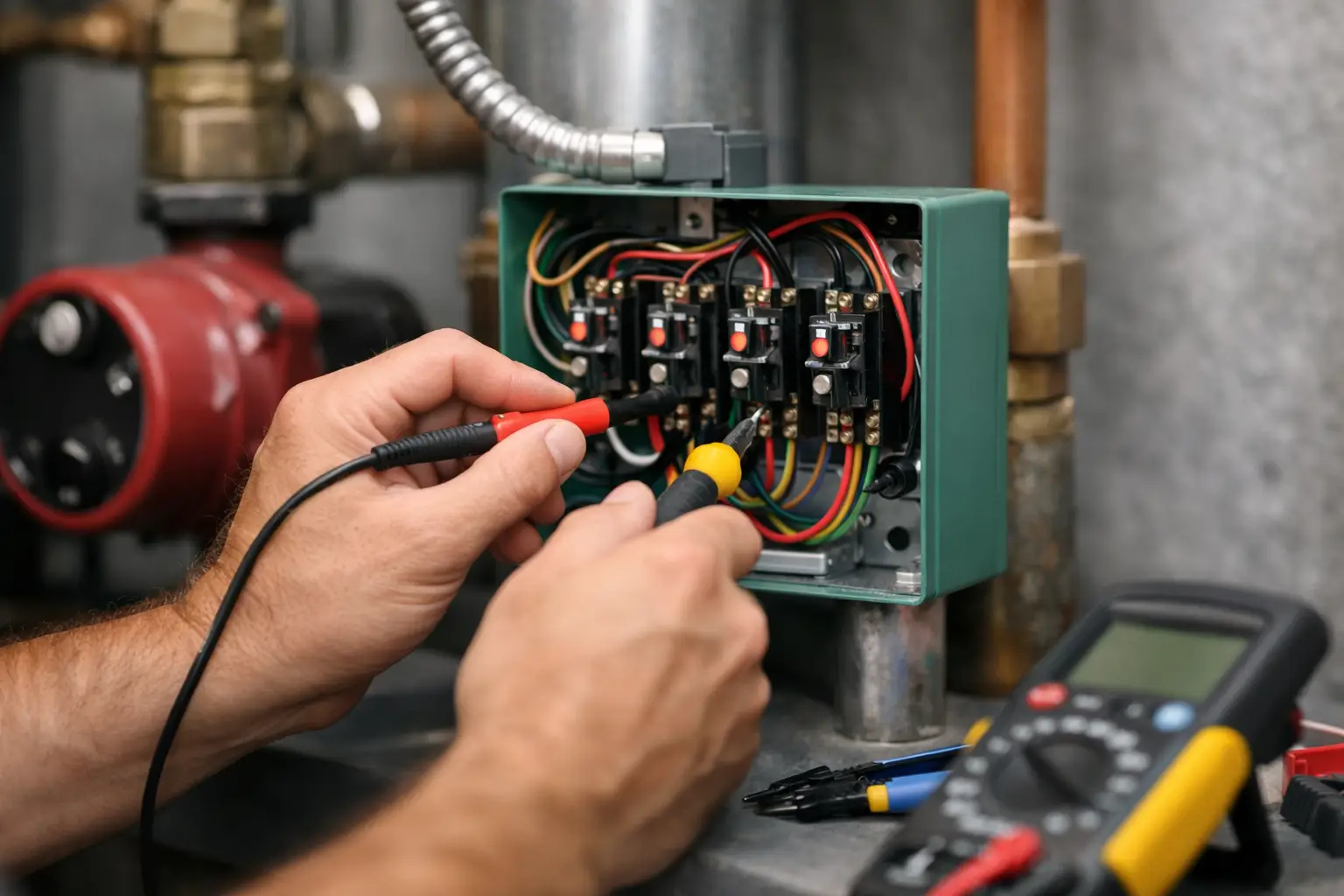
A circulator relay is a small control component with two jobs that must happen in the right order: it starts the correct pump and tells the boiler there is a call for heat. Knowing how to wire circulator relay controls correctly means separating 120-volt power wiring from 24-volt control wiring, then verifying the boiler receives a proper dry-contact call. Mixing those circuits, or assuming terminals are interchangeable between relay models, creates nuisance lockouts, burned transformers, and dangerous line-voltage faults.
Start With the Control Sequence, Not the Terminals
Before landing a wire, establish what the system is supposed to do. In a basic single-zone boiler system, the room thermostat closes on a drop in room temperature. That closure energizes the circulator relay. The relay starts the zone circulator and closes an isolated end switch. The end switch closes the boiler's heat-call circuit, often marked T-T, enabling the boiler and its own operating controls.
That sequence changes on some systems. A cold-start boiler may wait for the end switch before firing. A boiler with a tankless coil may use an aquastat that manages the burner independently of the space-heating call. A multi-zone relay panel may provide priority for an indirect water heater, delaying space-heating circulators while the domestic hot water zone runs. Wiring has to follow the intended sequence, not a diagram remembered from another job.
Read the relay's wiring diagram and the boiler control diagram together. Terminal designations vary by manufacturer and model, even when the enclosure looks familiar. Never treat a terminal marked X-X, T-T, C, R, or N as universal without checking the actual control documentation.
Identify the Four Circuits on a Typical Relay
A conventional single-zone circulator relay commonly contains four distinct circuits:
- A 120-volt line-power input that feeds the relay.
- A 120-volt switched output for the circulator.
- A low-voltage thermostat input that calls the relay.
- An isolated end-switch output that calls the boiler.
The equipment grounding conductor is part of the line-voltage side as well. It is not optional, and it does not land on a low-voltage common terminal.
A common arrangement is line power connected to terminals marked H, N, and ground, with the circulator connected to a separate H, N, and ground group. In many relay designs, the hot conductor is switched while the neutral remains continuous. That is a design detail to verify, not an assumption to make. The thermostat lands on a low-voltage pair, often T-T. The end switch lands on another isolated pair, often X-X, which is wired to the boiler's T-T or heat-demand terminals.
The thermostat circuit and the end switch may both involve 24 volts, but they perform different functions. The thermostat closes the relay's internal low-voltage circuit. The end switch is typically a dry contact: it simply opens and closes a circuit supplied by the boiler control. Do not feed 24 volts from one control into the other unless the manufacturer specifically shows that connection.
Safe Preparation Before Wiring a Circulator Relay
Lock out the boiler and circulator power at the service switch or breaker. Then prove the circuit is dead with a meter. A switch in the off position is not proof of a dead circuit, particularly when multiple circuits enter a boiler room or a control cabinet.
Confirm the branch-circuit voltage before selecting a relay. Most residential circulator relays and wet-rotor circulators are 120 volts, but 240-volt pumps, ECM circulators, and combination control panels require closer attention. Check the relay's voltage and amp rating against the circulator nameplate. A relay rated for a small fractional-horsepower pump is not automatically suitable for a larger three-piece circulator or multiple pumps.
Use proper connectors and listed cable clamps at every enclosure entry. Keep line-voltage conductors separated from Class 2 thermostat conductors. Maintain grounding continuity from the branch circuit to the relay enclosure and circulator. If the relay enclosure is metal, bond it according to the equipment instructions and applicable code requirements.
/center>Trace Existing Wires Before Removing Them
Replacement work is where mistakes multiply. Photograph the existing control, identify each conductor, and determine whether the old relay actually operated correctly. A wire on a terminal is evidence of a past connection; not proof it belongs there.
Trace the thermostat pair back to the thermostat or zone valve control. Trace the boiler call pair to the boiler aquastat, integrated control, or low-water-cutoff control as applicable. Trace the circulator cable to the pump. If more than one cable enters a junction box, use continuity testing with power off rather than guessing by jacket color.
How to Wire a Circulator Relay in a Basic Boiler Zone
With power verified off, mount the relay where it can be serviced and where its wiring compartment remains accessible. Bring the 120-volt feed, circulator cable, thermostat cable, and boiler-call cable into the proper compartments using approved fittings.
Connect the incoming equipment ground to the relay grounding point and connect the circulator ground as specified by the control. Connect the incoming line hot and neutral to the relay's designated line terminals. Connect the circulator hot and neutral to the designated circulator output terminals. Do not place the circulator directly on the incoming line terminals unless the design intentionally calls for a continuously running pump.
.Next, connect the thermostat pair to the relay's thermostat terminals. This is normally a dry closure from a conventional heat-only thermostat. Polarity usually does not matter for a simple mechanical thermostat, but follow the relay instructions when using electronic thermostats, powered zone controls, or special sensing controls.
Finally, run a dedicated two-conductor cable from the relay's end-switch terminals to the boiler's heat-call terminals. On many boilers, that means X-X at the relay to T-T at the boiler control. This connection should be isolated from the thermostat input. It tells the boiler that the relay has accepted a heating call and is ready for the boiler to fire.
Do not connect a 120-volt feed to boiler T-T terminals. Those terminals are normally low voltage. Applying line voltage can destroy the boiler control immediately and may damage connected safety controls.
Check the End Switch Before Powering the Boiler
The end switch is the most commonly misunderstood part of circulator relay wiring. It is a switch, not usually a voltage source. With power off, place an ohmmeter across the relay end-switch terminals. With no thermostat call, the switch should generally be open. Create a call according to the relay instructions or temporarily jumper the thermostat terminals only for a controlled test. The end switch should close when the relay operates.
If the end switch remains open while the circulator output is energized, the relay may be defective or the test setup may be incorrect. If it closes but the boiler does not fire, move the diagnostic process to the boiler heat-call circuit, safeties, limit controls, and ignition sequence. Do not bypass boiler safety controls to force a firing cycle.
Startup Testing With a Meter
After inspecting every termination, restore power and test the sequence one step at a time. Call for heat at the thermostat. At the relay, verify that the thermostat input is recognized. Confirm the circulator output has the correct voltage and that the pump starts. Then verify continuity through the end switch or verify the boiler receives its expected heat call.
A useful diagnostic rule is to measure across a switch or contact. A closed contact has little or no voltage across it because both sides are at nearly the same potential. An open contact in an energized circuit will show the control voltage across it. This method prevents the common mistake of measuring from an unknown terminal to ground and drawing the wrong conclusion.
Once the boiler fires, verify the circulator is moving water in the intended direction and that the zone heats normally. A correctly wired relay cannot correct a closed service valve, air bound loop, failed circulator cartridge, incorrect pump orientation, or an improperly set boiler control.
When a Basic Relay Is the Wrong Control
A simple circulator relay is appropriate for one conventional heating zone, but it is not the answer to every hydronic control problem. Multiple thermostat zones may need a multi-zone relay panel, individual zone relays, or zone valves with an end-switch arrangement. An indirect water heater may require priority logic. A variable-speed ECM circulator may require a specific switching method or a control signal beyond a basic on-off relay.
Also consider boiler manufacturer requirements. Some modulating-condensing boilers use dedicated demand terminals, pump outputs, low-water-cutoff interlocks, or communicating controls. A dry-contact end switch may still be required, but the exact connection point and pump logic can differ substantially from a conventional atmospheric boiler.
Good circulator relay wiring is not about making the pump run. It is about making the thermostat, relay, boiler, safety controls, and hydronic circuit respond in a predictable sequence. When that sequence is clear on paper before the wires are landed, the startup test becomes confirmation rather than a troubleshooting exercise.
For more information about boilers, air conditioning, Heat pumps and steam systems to get a limited time discount off my Practical Guide to Electrical Testing and Troubleshooting with Diagrams book please visit our website visit our website