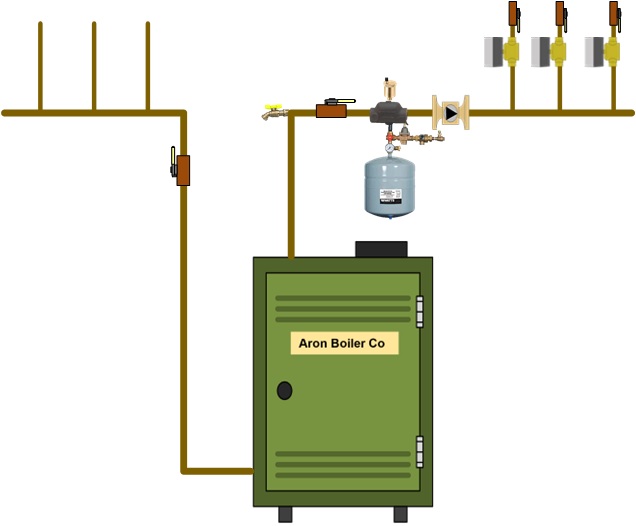
Standard Manifold Piping for older Cast Iron Boilers
Caution: All drawings are conceptual drawings for illustration purposes only and may be incomplete. Near boiler piping diagrams have not changed much over the years. Here is the way they used to be shown.

Standard Manifold Piping for current Cast Iron Boilers
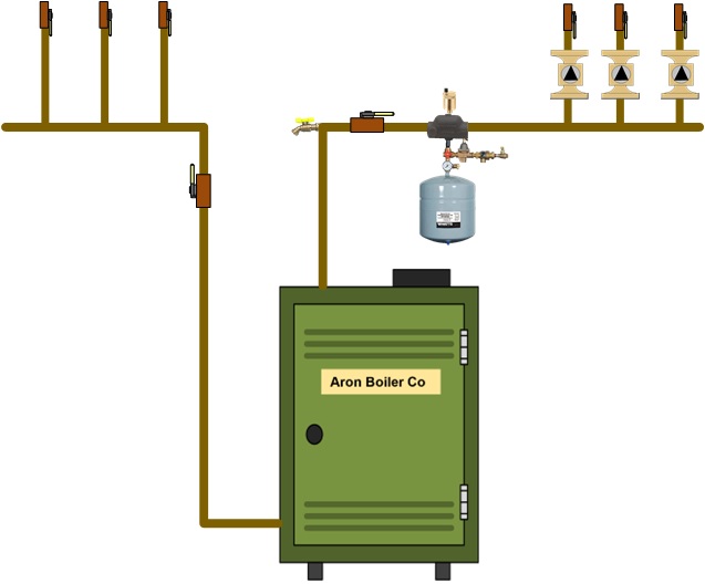
The changes in the above drawing are the placement of the purge valves, ending the manifold with tees instead of elbows, and a drain on the supply header and possibly on the return header, circulator placement, to name a few. The make-up water should always be placed between the expansion tank and the system. Let's look at what advantages we have over the manifold of yesteryear. We have a single purge drain on the boiler riser instead of one for each return pipe. This is more service-friendly than the older style. The valves above the flow checks can all be closed; close the feed valve and the supply manifold valve. You can now drain off a little bit of water that is isolated between the closed valves. We can service the circulators, flow checks (not shown), zone valves (if used), check the air charge on the expansion tank, air separator, and air vent, and perform service/replacement without losing much water, and may not need to be purged. When the service is complete, open the fill valve first. Secondly, open one of the valves on any zone or zone valve. Run the circulator for that zone. Since we are pumping away from the expansion tank, normally, no purging is needed. We have not allowed enough water into the piping to stop the flow. The pump will break the air into smaller bubbles by adding pressure to the zone. The smaller, less buoyant air bubbles work their way to the boiler, where the water is being heated and the air is being driven out of the water. The water and air are separated in the air separator, where the air is vented. Continue the same steps with all the remaining zones, pack up, and go home. There's no need to purge the heating system again unless you need to completely drain it of all water. There are variations of the above drawing if you keep the same idea. You may use a circulator and zone valves instead of multiple circulators and flow control valves. You can choose circulators with internal flow checks rather than those with flow control valves. Consider using circulators with internal flow checks and flange isolation flanges, and eliminate the flow checks and shut-off ball valves. Please keep in mind that the primary goal here is to provide ease of service. Disclaimer: The information found on this website is for informational purposes only. All preventive maintenance, service, and installations should be reviewed on a per-job basis. Any work performed on your heating system should be performed by qualified and experienced personnel only. Comfort-Calc or its personnel accepts no responsibility for improper information or application, damage to property, or bodily injury from applied information found on this website.