
Buffer Tank - A Different Idea
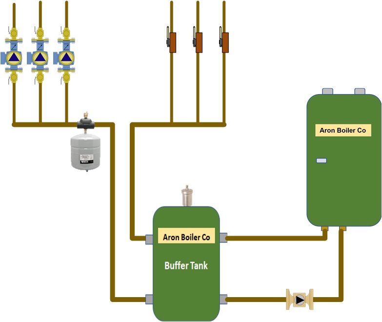
All the piping diagrams on this website are simplified and do not include any devices required for actual installation. Please apply standard installation practices.For decades, buffer tanks were piped using the four tapings, two for the boiler and two for the system. Recently, that has started to change. Instead of using all four tapings, many jobs now use two, three, or all four. You may also not want to maintain a constant tank temperature, but instead let it heat according to the zone's demands. If you pipe a two- or three-pipe tank application, I usually wouldn't maintain the tank temperature, depending on the application. This allows the use of a buffer tank for an alternate system temperature, rather than using a mixing valve. For instance, if you have a high-temperature system and a small radiant load, the tank can maintain a lower temperature for the radiant load, eliminating the need for a mixing valve. The advantage of this would be that it has no moving parts. See the drawing at the bottom of this page. In a four-pipe application, I would consider maintaining the tank temperature. When you apply a buffer tank to a system, be aware of how to pipe the IWH into the system.
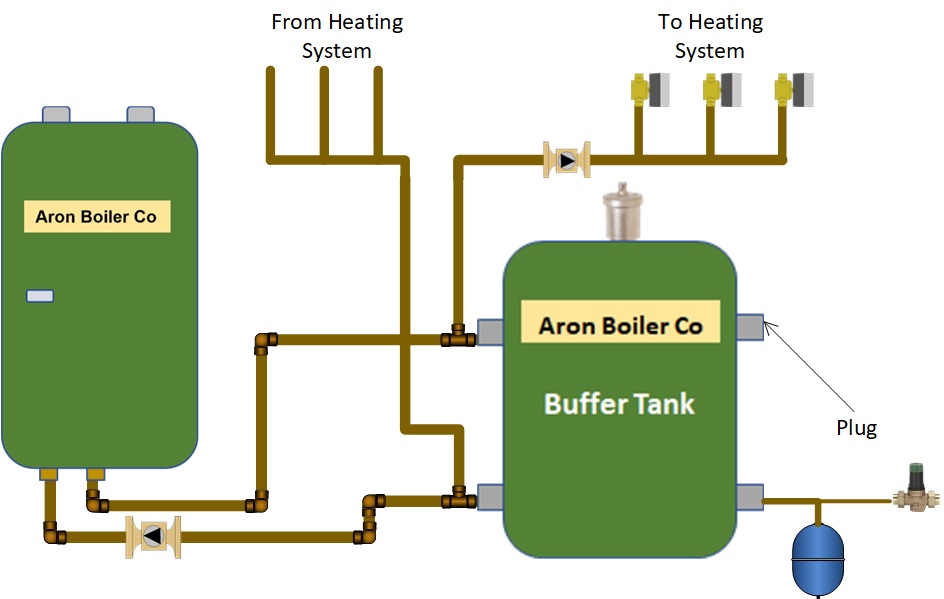

When another zone opens in this example, the flow to the system is equal to the required flow in the system, and no water flows through the tank.

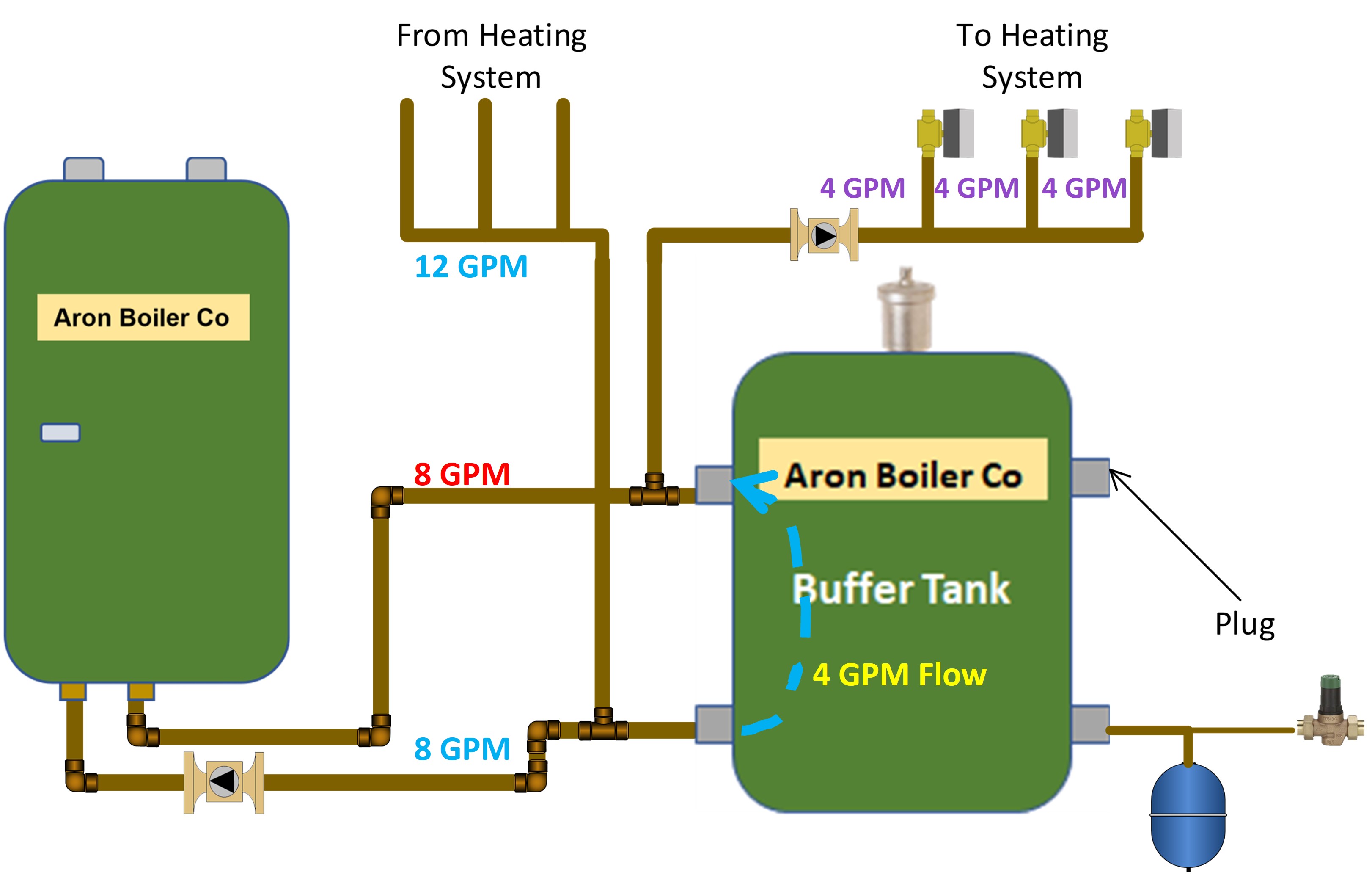
Next, when all the system zones are in demand, the system flow rate will exceed the boiler flow rate. As shown in the text, the GPM flow is purple, and the water temperature is lower than the boiler supply temperature. We will be adding a cooler return temperature through the tank; however, as the supply temperature increases, the return temperature also increases. Another advantage is that during most of the heating season, your demand will not be in all zones, so the tank temperature will store hotter water than it would with a cold start.
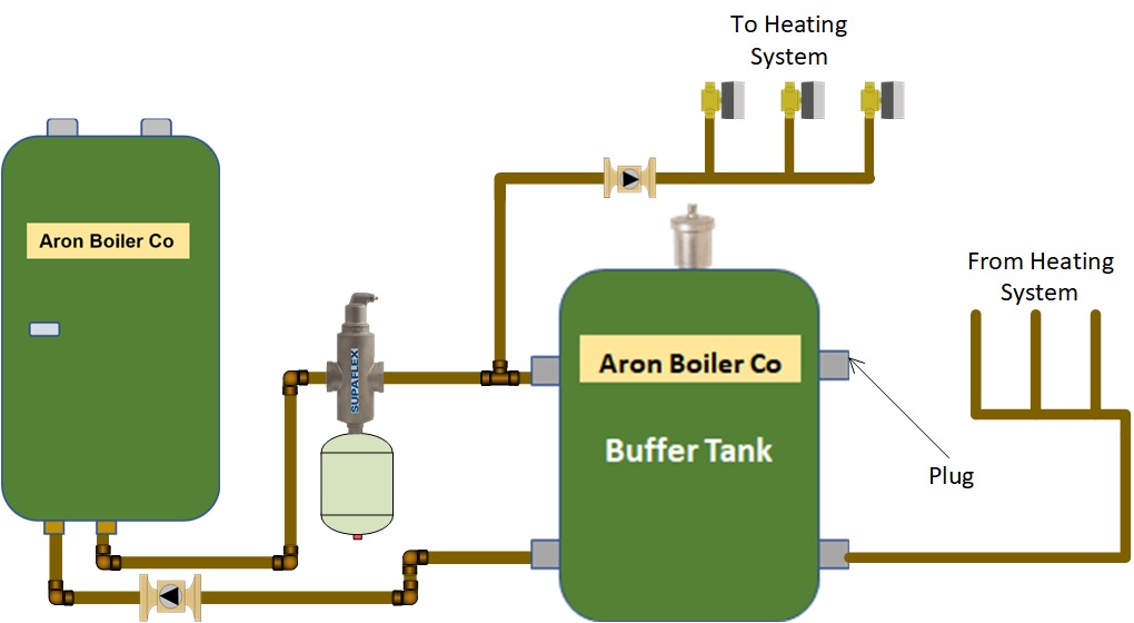
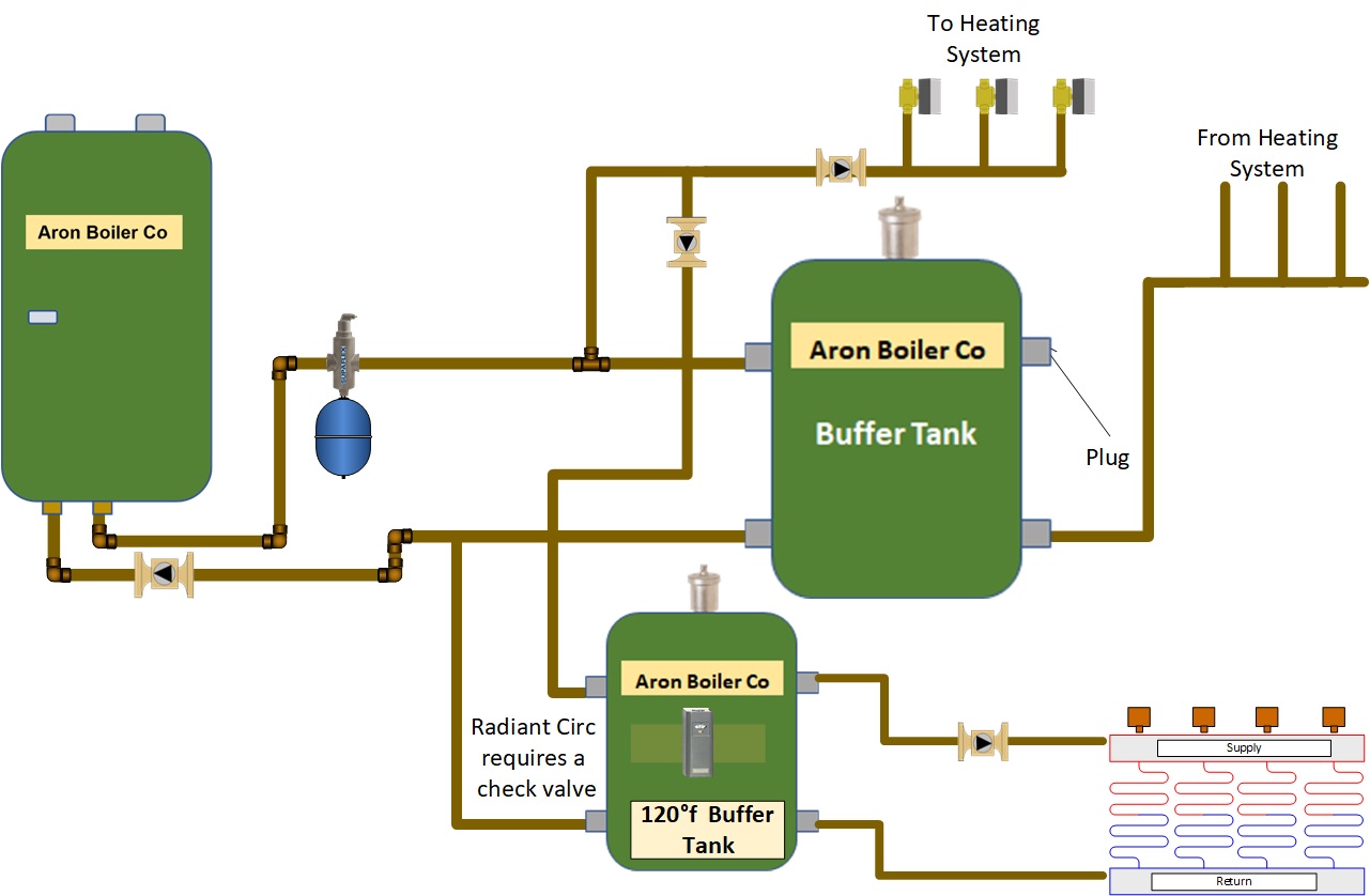
While we are thinking out of the box, here is another way of using buffer tanks
Another scenario is that there is some low-temperature radiant in a home that also has high-temperature heating, like copper tube baseboard and/or hydro-air. The radiant could be added to the system with an aquastat to limit the tank temperature to approximately 120F. We would not want the radiant supply pipe before the tank, as in the examples above, because the water would be too hot for the low-temperature radiant system. Use all four tapings on the tank, two for the boiler loop and two to the radiant heat loop(s).
Using this application, all the radiants on the tank would have to be able to heat effectively, using the same water temperature. Since the tank temperature can be set using the tank aquastat, there would be no need to mix the radiant. I would use the aquastat as a limit control to set a maximum temperature for radiant heat application. The setting would be dependent on the radiant heat application. Wire the aquastat in series between the radiant zone control and the boiler demand terminals. Most high-efficiency boilers today have more than one heat input terminal, and some even allow multiple temperature outputs. If not, piggyback the single heat demand terminals.
Do not piggyback on DHW terminals, as this is not a priority for us. If you do not have an IWH, you can use the DHW terminals, but ensure that you turn priority off. Applying this piping to any other zone, it is critical to properly size the circulator for the radiant buffer tank. Of course, as with any piping application, you may have to change the piping slightly. Do not. This may also require changing the pump setting in the pump parameter.
Disclaimer: The information found on this website is for informational purposes only. All preventive maintenance, service, and installations should be reviewed on a per-job basis. Any work on your heating system should be performed only by qualified, experienced personnel. Comfort-Calc and its personnel accept no responsibility for improper information, application, damage to property, or bodily injury from applied information found on this website.