Drawings on this page are from my online or live seminar
Calculating Fuel Pump Vacuum
Before we get into figuring a pump vacuum let's look at the different pumps. In our example we will look at Suntec pumps and all others work the same. The difference if what vacuums the pumps will work at through different manufacturers. Suntec has many pumps, but we will look at just a few new and old pumps. A fuel pump will work as a 1 pipe or two-pipe system. Installing a two-pipe system will give you more lift (high vacuum) if needed. There is also one stage and two stage fuel pumps.
A single stage pump will have one set of gears to pump oil from the tank to the oil burner and if a two pipe fuel system the same gear set will return oil to the tank.
A single stage pump can be operated in a one pipe or two pipe oil system, as long as we include a bypass plug when needed. Most manufactures require it when using a two-pipe application. The advantage of piping a single stage pump in a two-pipe application is less cost than a two-stage pump and will operate at a higher vacuum than a single stage one pipe system. The vacuum will be less than a two-stage pump can create.
There are also 2 stage pumps which will pump oil to the burner with one set of gears and return oil back to the tank with a second set of gears. A two-stage pump should always be piped using a two-pipe system. If piped with a single pipe it will produce about the same vacuum as a single stage one pipe system. We will only be discussing the Suntec Mini pumps here since they are the most common residential fuel pumps. If you have a different fuel pump you will need to use your fuel pump manufacturer information for other type fuel pumps.
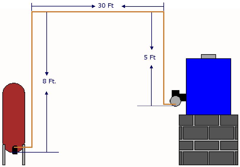
A good rule of thumb calculation is as follows:
1" of vacuum for every 10 ft of horizontal run
1" to 2" of vacuum for the valve and filter combined dependent on what type of filter you're using
Calculate the vacuum for other devices in the line like check valves etc.
Here is an example. What would the pump configuration be?
Here is an example of the calculation
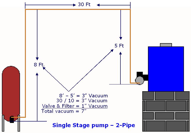
We have chosen the pump from the chart below. The single stage pump will work as a two-pipe system. It exceeds the one pipe rating of 6" of vacuum but is within the two-pipe single stage pump vacuum of 12". Now we have an idea of what the vacuum should be when checked.
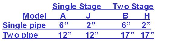
Chart from Suntec (2014)
If the vacuum is less than our estimated vacuum by more than 2", we may very possibly have an air leak at one of the fittings, pump cap, or pump plugs. If you're an old timer like me and still have an electronic sight glass you can use this to pinpoint an air leak. See
If you get a higher reading, I'd look at the following items but not limited to this list.
2. Check the number and types of fittings, too many fittings increase pump vacuum. Make sweeping bends instead of using brass elbows where possible.
3. Condition of filters and strainers, verify they are clean.
4. Condition of valves, make sure they are full open and use full port fuel valves.
5. Contaminate build-up on inside walls of lines, clean lines if needed and possible. Do not blow out underground fuel lines. They may rupture and you will not be aware of it.
Disclaimer: The information found on this website is for informational purposes only. All preventive maintenance, service, installations should be reviewed on a per-job situation. Any work performed on your heating system should be performed by qualified and experienced personnel only. Comfort-Calc or its personnel accepts no responsibility for improper information, application, damage to property or bodily injury from applied information found on this website.