
Primary/Secondary Piping Tutorial
- 1. Hydraulic Separation
- 2. The flow of one circulator does not affect the flow of another circulator
- 3. Guarantees the proper flow through the boiler not dependent on system flow
- 4. Allows multiple Delta-T's within the heating system. For instance, system could be one delta-T and the boiler could be at a different Delta-T if required
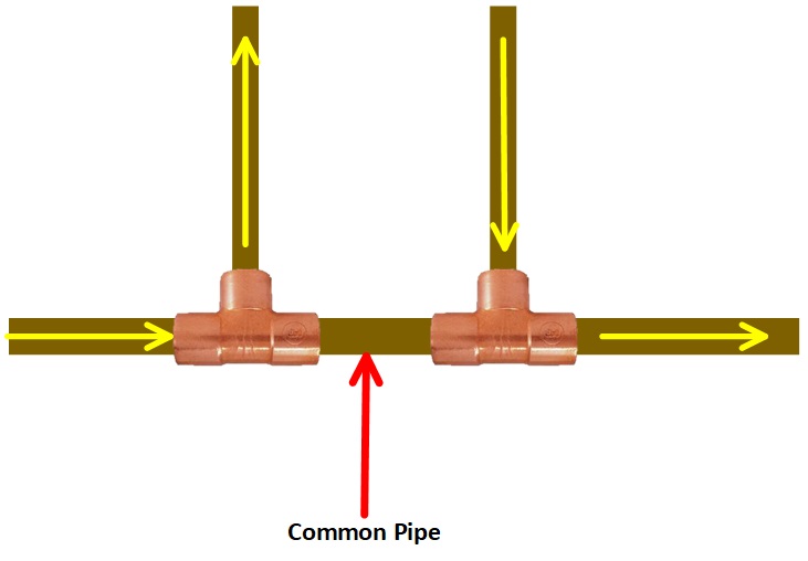
Gill Carlson, the grandfather of P/S piping said in the Primary/Secondary Pumping Manual, "When two piping circuits are inter-connected flow in one will not cause flow in the other if the pressure drop in the common piping to both is eliminted."
The common pipe is a short piece of pipe that fits between two closely spaced tees.
Hydraulic separation allows several circulators of different pumping flow rates to coexist within the same system without interfering with each other. The closely spaced tees allow each circuit to be thought of as a separate or standalone circuit. The tees should only be installed end to end so the primary flow is straight through the run of the tees. A pump flow in a given circuit of a P/S system is not affected by any other circulator in the system, even if different size circulators are existing.
The primary pipe is the pipe where common pipe is installed, and the secondary piping is the circuit piped off the branches or bulls of the closely spaced tees. There are rules we must follow when piping P/S systems if we want them to work well.
Drawing 1
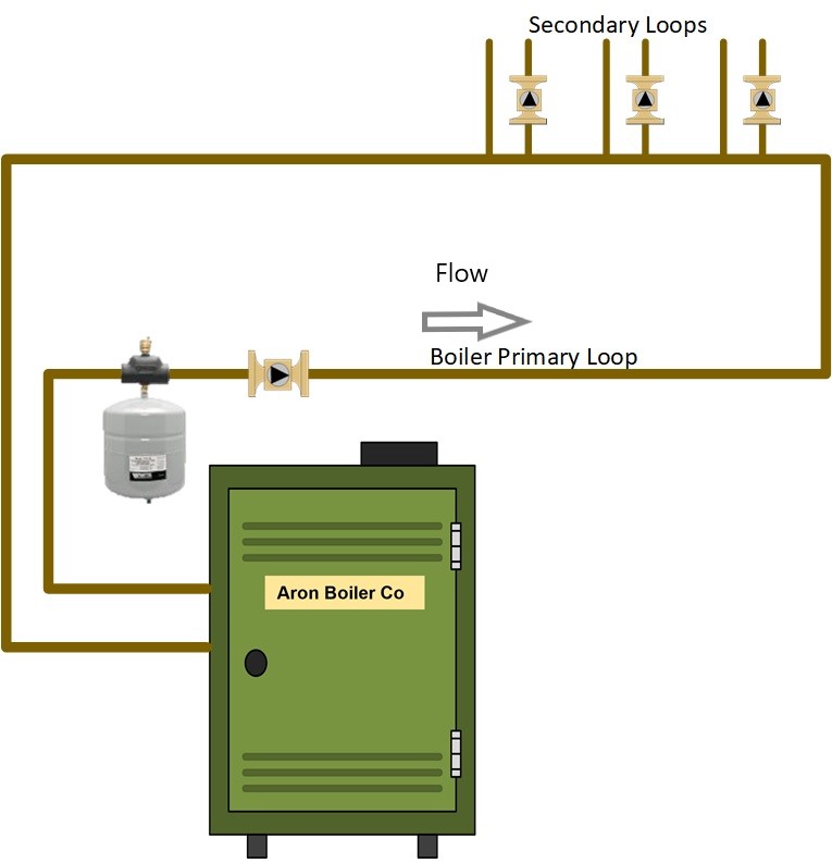
In this example the pipe coming from the boiler is the primary pipe as it includes the common pipe. The water will leave the boiler and return to the boiler through the connected loop. As the secondary circuits (piped off the closely spaced tees) are running, the water temperature in the primary pipe will decrease after any running secondary zones.. This diagram is best when applied to a system with multiple system water temperatures.
The secondary piping would be arranged so the hottest shortest loop is first, the longest coolest loop is last from right to left in this drawing. This may be an example of a baseboard loop first, a large cast iron loop second, and a radiant floor loop last on the left.
Drawing 2
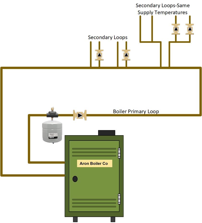
This is the same as the previous drawing where the boiler loop is the primary pipe. The only difference here is I am showing how to pipe two secondary zones of the same water temperature. The zones to the left will receive lower supply temperature. See more information if this is cast iron boiler installation as we will need Protection against flue gas condensation. If this installation is a modulating condensing (mod/con) boiler, we would not be concerned about condensing because we want the cooler water returning to the boiler for higher efficiency. The cooler the water the more efficient the mod/cons run. The cast iron boilers would be destroyed by condensate from return temperatures less than 130f.
Drawing 3
In this drawing the primary pipe, again being the one with the closely spaced tees would be the primary loop. There are four secondary heating zones on the top and of course the boiler is a secondary zone on the bottom.
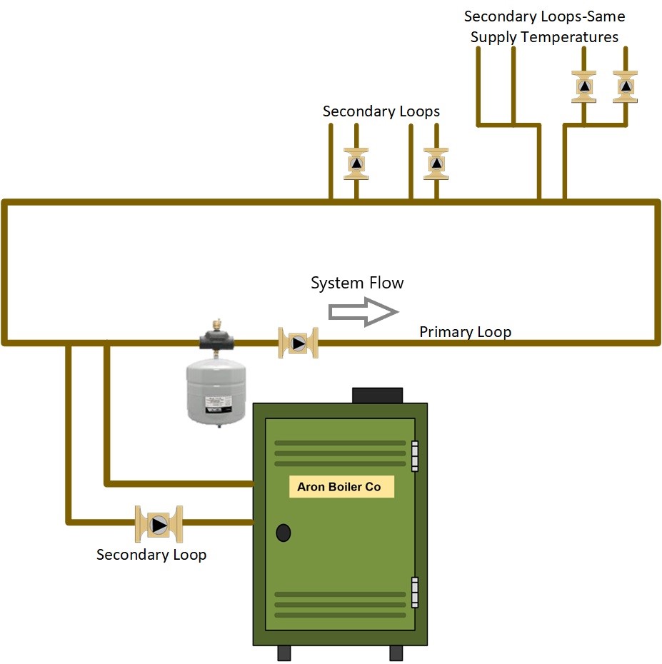
Drawing 4
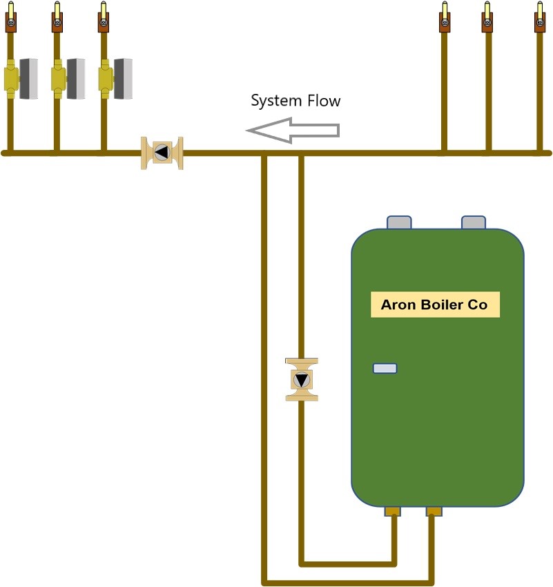
This is also P/S as it is connected with closely spaced tees for the boiler connection. The boiler would be considered secondary piping as it is piped out of the branch of the closely spaced tees. This piping is a good application if all the zones are looking for the same temperature water. The piping around the close spaced tees should be of ample size to allow proper flow in either direction.
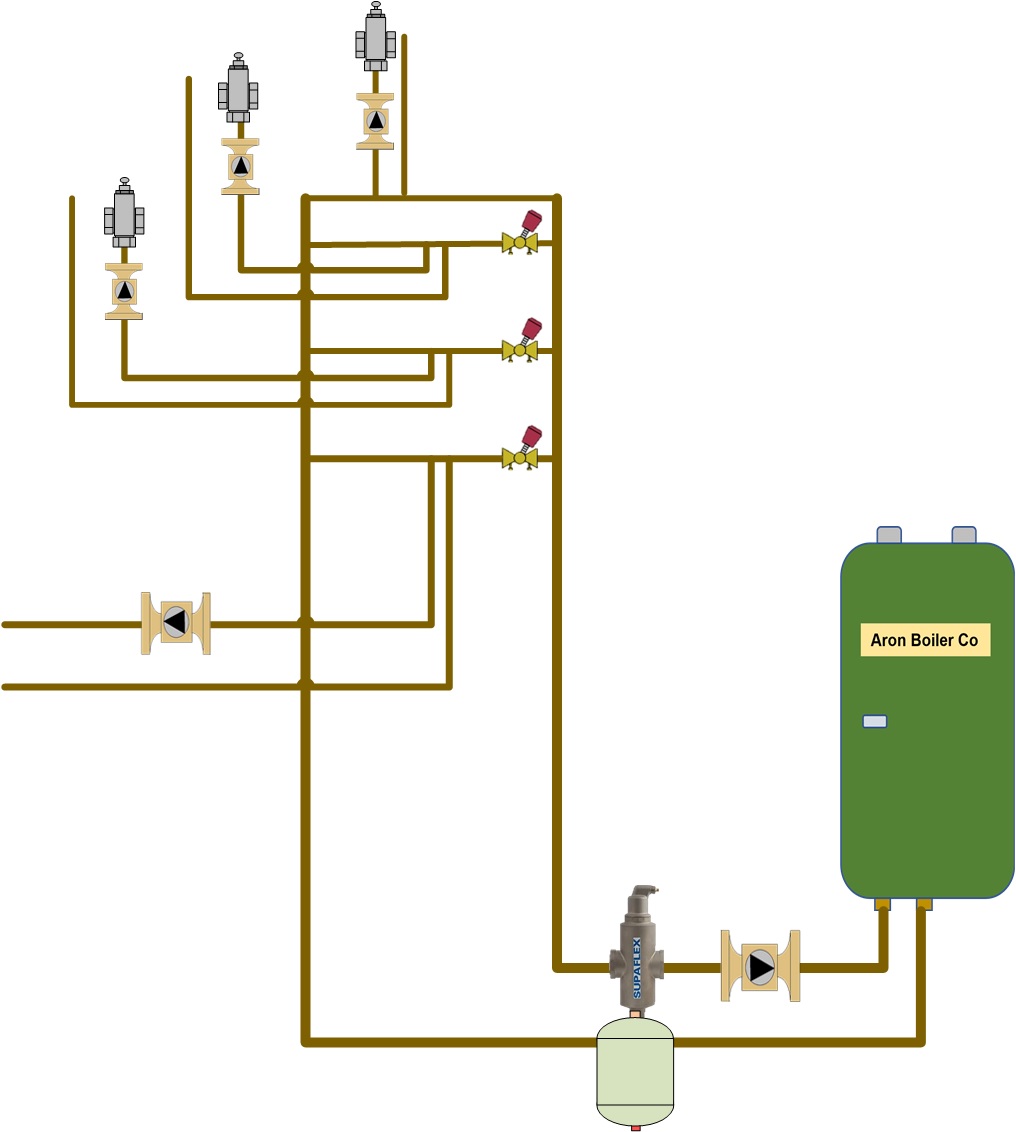
Drawing 5
 <
<
This drawing shows a device called a hydraulic separator. It will take the place of closely spaced tees and common pipe. The advantage of the hydraulic separator is it will offer air elimination and possible dirt elimination on the bottom (not shown) along with hydraulic separation.
Drawing 6
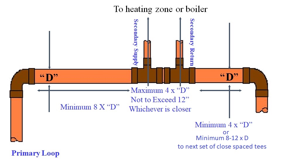
The first rule when installing close spaced tees is they must be mounted end to end. If piping the boiler with close spaced tees the system flow must travel through the run of the tees, (see drawing 4), not the boiler water. Boiler water should flow in and out of the bull or branch of the tees. If using close spaced tees on a primary loop, it is important to follow these measurements. The boiler or heating zones can be piped as secondary piping and would follow the distance between the closely spaced tees. The most confusing is the distance between the closely spaced tees. You need to follow 4 x the diameter of the primary pipe rule. It does not mean you have a choice somewhere between 4 x dia. and 12". It means you follow rule one, if the result exceeds 12" you apply rule # 2, Do not exceed 12". For example, 4 x 2" pipe is 8", this is the maximum distance between the tees. Four times 3" pipe is 12" maximum. Four times 4" pipe is 16" you cannot exceed 12". Never put anything between the tees. This will create a larger pressure drop between the tees and create ghost flows. The best idea for the tees is as close as you can get them all the time on any given pipe size. The minimum distance between multiple sets of closely spaced tees is 8 - 12 pipe diameters.
Flow in the Tees
The second rule is all the water in the piping starts to move at the same time. Look at the drawings below and look at the difference in flow rates between the tees. Pay special attention to the last drawing #9.
Drawing 7

In this first example the primary loop is moving 10 GPM. When the secondary loop circulator starts all the water starts to move at the same time in the secondary loop. It steals 5 gpm from the primary loop and the other 5 gallons continue between the tees. In the second tee the two 5 GPM flows join, and the flow continues in the primary loop at 10 gpm. The primary circulator had no clue this even happened as it did not affect the flow in the primary loop. It does not know the secondary circulator is even there much less any flow happening in the secondary loop. The only thing going on with the primary circulator is it is getting 10 GPM and is discharging 10 GPM into the loop.
Drawing 8

In this example the secondary circulator is pumping the secondary loop at 10 GPM. The flow in the secondary and primary are equal. As the 10 gpm enters the tee all 10 gallons passes out the branch and there is technically no flow between the tees. When the flow enters the return tee all the water goes to the right and there is 10 gpm flow in the primary loop to the primary circulator.
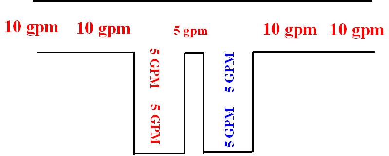
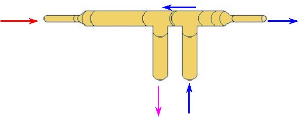
Drawing 9
In this example it is important to remember the two rules. What enters a tee exits a tee and all the water in the piping moves at the same time. The primary loop is moving 10 GPM. The secondary will move more than the primary loop. It wants to move 12 GPM. As 10 GPM enters the tee from the left and the circulator starts it takes all 10 GPM the primary loop circulator will supply. As the secondary circulator starts all the water in that piping moves at the same time so it dumps 12 GPM into the tee on the primary loop. The primary loop circulator takes away 10 GPM of the 12 GPM leaving 2 GPM to reverse flow between the tees and mix with the 10 GPM entering the tee from the primary circulator thus giving us the 12 GPM flow needed on the secondary loop. If this is designed this way it is a good thing. Unfortunately, this happens by accident more than design. If not part of the design the temperature in the secondary loop has a hard time getting hot enough to satisfy the load. In most cases the temperature of the water entering the pipe will be the same temperature of the water between the tees. If this is not so you have reverse flow. The reverse flow would take place in the radiant low temperature zone. Pay attention to the arrows.
The question is "Was it designed that way or not?
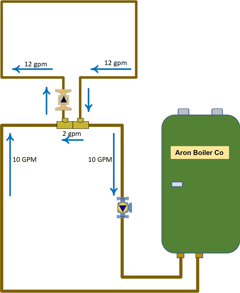
Drawing 10
You may, at times see something like this. All the supply temperatures in the crossover pipes will all be the same as we see in the manifold piping in Drawing #4. This will allow enough backward flow between the tees to blend the secondary water temperature down to where it needs to be. This will not affect the flow on the crossover pipe. The flow between the tees may be greater than the flow into and away from the tees. This will normally be used in what we call crossover piping or Primary/Secondary Parallel piping. This is normally used when one circulator is larger, moving more water and sized for higher head than the other circulators.
When the need for a higher head pump is needed and this was piped on a manifold as shorn in drawing #4 the larger could pull water through the smaller zones or reduce the flow through the zones with smaller circulators.
Disclaimer: The information found on this website is for informational purposes only. All preventive maintenance, service, installations should be reviewed on a per job situation. Any work performed on your heating system should be performed by qualified and experienced personnel only. Comfort-Calc or its personnel accepts no responsibility for improper information, application, damage to property or bodily injury from applied information found on this website as it should be reviewed by a professional.