Variations of Primary/Secondary Boiler Piping Ideas
Note: All drawings are conceptual drawings for illustration purposes and may be incomplete. More specific drawings may be required for your application. Refer to the manufacturer's installation manuals
The way a high-efficiency boiler is piped is determined by the application. Do you have different water temperature zones, or is the water temperature uniform throughout? Do you have an indirect water heater? Several factors need to be considered when designing the boiler piping layout. While cast iron boilers are very forgiving, the new high-efficiency boilers are not. I have seen many homeowners install cast iron boilers, and while some did a good job, many were awful. High-efficiency boilers should be left up to the professionals.
The drawings below are all piped differently. Why? The flow rate is a key factor, whether your zoning is for an indirect water heater or not.
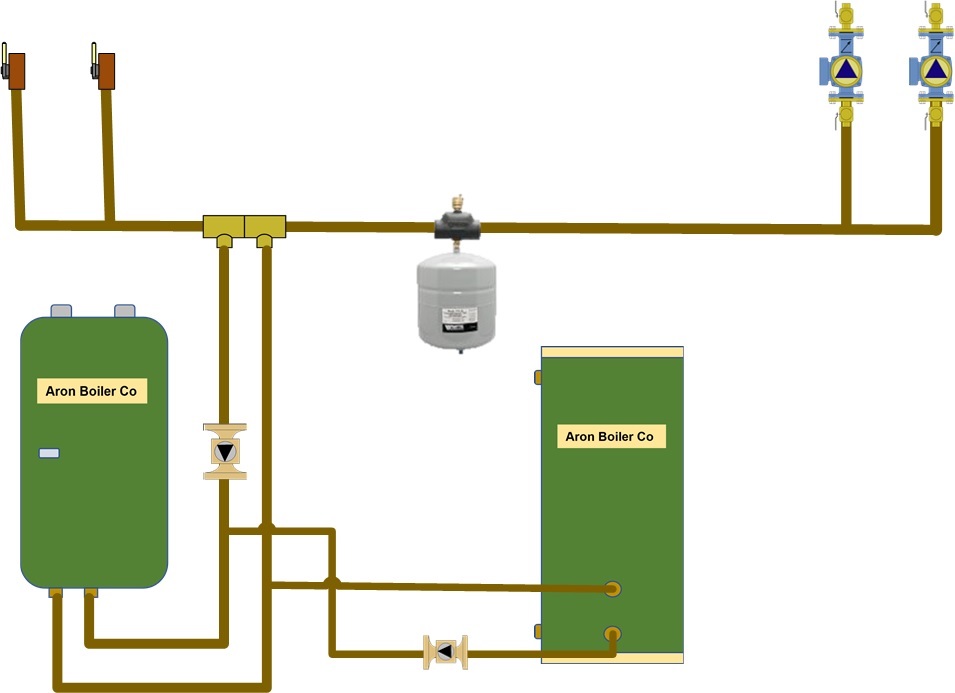
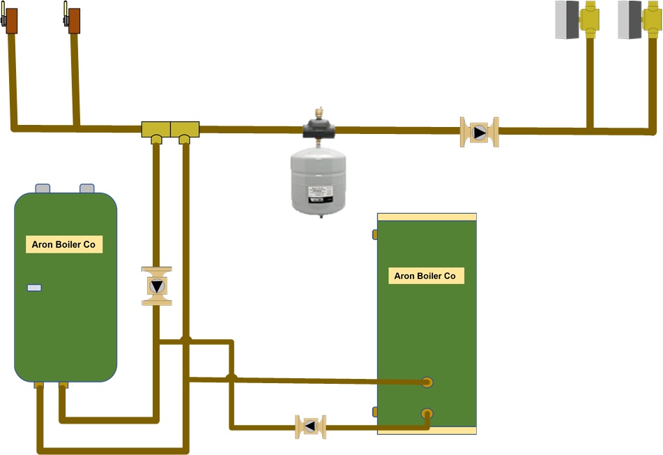
Drawings #1 and #2
Drawings #1 and #2 - Is a system using circulators or zone valves# for zoning. All zones should have the same water temperature. This involves removing the old boiler, connecting the supply and return manifolds, and installing a set of closely spaced tees for the boiler piping.
Fig. 1- Zoning with circulators
Fig. 2 - Zoning with Zone Valves
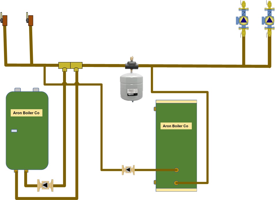
Drawing #3 - No IWH
Drawing #3 is named a boiler primary loop with system circulators. This means a pipe leaves the boiler supply taping, loops, and enters the boiler return taping. All the zones originate from the closely spaced tees on the side of the tees. The closely spaced tees separate the boiler flow from the system flow, a phenomenon known as hydraulic separation. The primary loop's temperature is affected by the running zones. The first zone gets the hottest water. When the additional zones are running in conjunction with the first zone, they will receive cooler water. This is OK if the zones require lower water temperatures as we go around the loop. In this drawing, the second baseboard zone will receive water that may be too cool to heat the zone properly.
The rule is to start with the shortest, hottest zone and end with the coolest, longest zone. Remember, a mixing valve may still be required for zones that receive cooler water, such as an in-floor radiant system in a concrete slab.
Fig. 3 - Boiler Primary Loop All zones drop in temperature
Drawing #4 and #5 - No IWH
This is the same drawing as #3 except multiple zones on the first set of close-spaced tees. This method achieves a uniform temperature distribution across the zones, whether zoned by pumps or zone valves, when piped through this small manifold. The reason is that all the zones have the same water temperature. If they are both baseboards, they want the same water temperature. Anything beyond the first set of closely spaced tees will receive cooler water if any or all of the zones off this manifold are running.
Fig. - 4 - Same temperature zone manifold, zoned with pumps
Fig. 5 - Same temperature zone manifold, zoned with zone valves
Drawing #6 and #7 - No IWH
These are similar to Fig. #1 and Fig. #2, but we added an Indirect Water Heater (IWH) shown with circulators and zone valves. Note, the drawing with zone valves still shows the IWH with a circulator. I believe that is the best way to maximize hot-water recovery in the tank. These drawings were popular when high-efficiency boilers were first introduced into the USA. Since then, IWH piping has changed, with many manufacturers offering different options.
Two critical things in the hydronics industry are Flow and Resistance to flow (pressure drop). Everything has a pressure drop: piping, fittings, valves, boilers, coils, and so on. If the water passes through it, it creates a pressure drop or resistance that slows down the water flow. The problem I have with these drawings is that the flow requirement for the IHW tank and the boiler may vary too much.
If the flow in the IWH is insufficient, recovery will be slow. If the boiler flow is too low, the boiler water could flash into steam or cause damage to the boiler. The boiler will attempt to modulate down, but may not be able to do so quickly enough.
Fig. 6 - IWH connected to boiler piping, zoned w/pumps
Fig. 7 - IWH connected to boiler piping, zoned w/pump, heating zones w/zone valves
Drawings #8 and #9
Is another variation of drawing Fig. #6 and Fig. #7. The key difference is that the known flow through the boiler and indirect system is significantly different. With the closely spaced tees, you set up hydraulic separation, so the flow of the indirect water will not affect the boiler flow. Each appliance will receive its proper water allocation.
Fig. 8 - IWH piped on System Piping, all zoned w-pumps
Fig. 9 - IWH piped on system piping, Heat zones w-zone valves, IWH w-pumps
Drawings #10 and #11 with IWH
These drawings show the boiler primary piping again. It is similar to Figs. 4 and 5, except with an IWH. Hydraulic separation allows the flow to be different between the boiler and the indirect water heater. I am also showing a mix of circulators and zone valves. The IWH is the first to receive the hottest water when DHW is not prioritized, which I would suggest for this type of piping.
The zone valves are on a couple of high-temperature zones, which both have the same temperature. The second set of closely spaced tees will be a cooler hydro-air zone. The last set of closely spaced tees will be the coolest zone, a radiant heat floor zone. It is not uncommon to add a mixing device for a radiant zone. It will likely have a mixing valve or injection to control the water temperature below a maximum level. All the heat zones will shut down on a call for domestic hot water if wired to do so. Just because the boiler control shows DHW priority is on, it may not shut down the heat zones if the boiler does not control the heat zone pumps.
Fig. 10 - Boiler primary loop, IWH first zone, heat zones pumps
Fig. 11 - Boiler primary loop, IWH first zone, heat zone valves
Drawing #12 and #13
Drawing #12 is my go-to drawing for retrofitting a high-efficiency boiler into an existing system and adding an IDW. In this drawing, you may or may not use DHW priority, depending on whether the boiler is oversized. The drawing can be used with circulators and zone valves.
As a side note, all these drawings on this page can also be applied to a cast-iron boiler installation, if you prefer.
Mod/con boiler piping is not limited to these drawings. There are more variations. As I mentioned earlier, flow and pressure drop are crucial. Water is best moving at a velocity of about 2 ft per second. Too slow or too fast, you will reduce heat transfer and may create piping noise.
One of the biggest differences with the drawings is what circulators should be running. Is the boiler circulator supposed to be on or off? Is the primary circulator running or not? Hmmmmmmmm!!!!! Maybe best left to the professional.
Disclaimer: The information found on this website is for informational purposes only. Any preventive maintenance, service, or installation should be reviewed on a per-job basis. Any work on your heating system should be performed only by qualified, experienced personnel. Comfort-Calc or its personnel accepts no responsibility for improper information, application, damage to property or bodily injury from applied information found on this website as it should be reviewed by a professional.