
Cast Iron and Steel Boiler Protection from Condensation
At the time of the original composition, the residential heating industry was markedly different from today. Most boilers were constructed of cast iron or steel. The early 2000s saw the introduction of high-efficiency aluminum and stainless-steel boilers, commonly referred to as modulating-condensing (mod-con) boilers. These advanced materials offered superior resistance to flue gas condensation compared with traditional cast iron or steel, effectively addressing prior concerns about durability. Adoption rates for these boilers rose substantially, and by 2020, more than half of residential boilers installed in the United States were high-efficiency models.
A key distinction between boiler types is that prolonged flue gas condensation can adversely affect cast-iron boilers, depending on installation practices, radiation types, system water volume, and operating temperatures. In contrast, the design of mod-con boilers significantly mitigates the risks of corrosion failure. There are established guidelines for installing cast iron or steel boilers, which are sometimes overlooked in practice.
Important concepts include Boiler Bypass, System Bypass, Delta-T, buffer tanks, and Primary/Secondary piping. Variable-flow circulators may be configured for either minimum return water temperature or delta-T circulation, using 3-way or 4-way valves and ESBE thermic valves. These strategies serve to protect boilers from condensation-related premature failure. The optimal protection method should be selected based on the return water temperature and the duration of exposure to lower temperatures.
Delta-T - refers to the temperature difference between the hot supply and the cool return, showing either a rise (boiler) or a drop (system). In North America, residential systems typically see a 20F drop, while boiler Delta-Ts range from 20F to 40F.
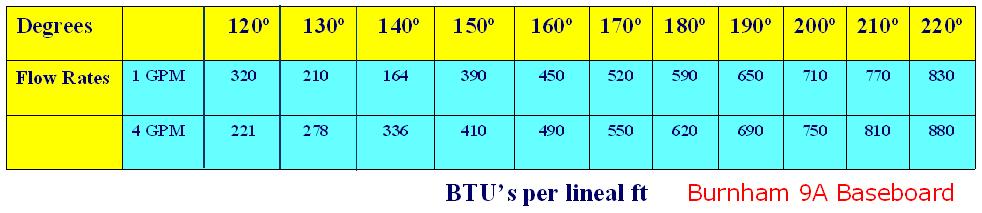
Flue Gas Condensation - occurs when the boiler water is cooler than the flue gas, typically when the return water is below 130F. This can be managed by adjusting temperature and flow. In cast-iron or steel boilers, the flame temperature stays the same, and lower water flow increases the heating rate, while higher flow reduces it but may prolong condensation.
Bypass Piping - is crucial to implement protective measures for cast-iron or steel boilers to mitigate thermal stress and prevent corrosion caused by flue gas condensation, which can lead to premature boiler failure. Boiler protection should be considered under several conditions, including:
When the boiler DOE output (gross output) is less than the total system radiation output.
For installations in these categories, careful attention must be paid to boiler protection strategies. There are two primary types of bypass piping: boiler bypass and system bypass. The boiler bypass is intended to maintain a higher system flow rate compared to the system bypass. This increased flow rate enhances heat transfer from radiation at a given water temperature; as water velocity increases, so does heat output, while a decrease in water velocity reduces it.
Prior to any critical assessment, please note that this methodology will result in fuel savings, though these may be modest in high-volume water systems, and will improve comfort levels. In systems with lower water volumes, the impact may be less pronounced. Many of the topics addressed herein may yield only incremental reductions in fuel consumption; however, by implementing most or all of the recommended strategies, greater cumulative savings can be achieved.
Boiler Bypass Piping
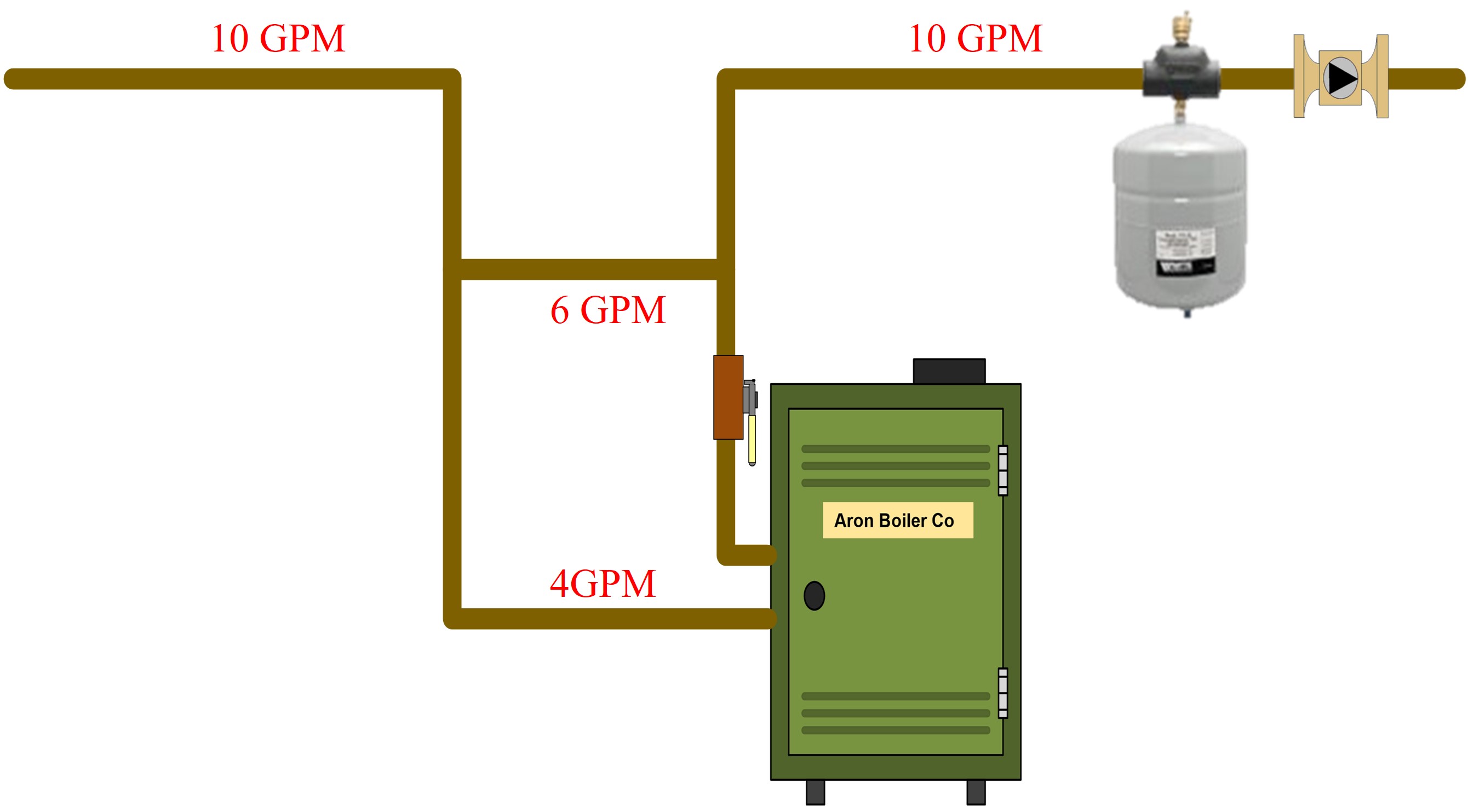
This method is implemented to safeguard cast iron or steel boilers from instances of light to moderate flue gas condensation. A boiler bypass pipe is a cost-effective option for this purpose, though it may not provide the most comprehensive protection. The boiler bypass diverts cool return water from the heating system directly to the supply line, allowing it to re-enter circulation without passing through the boiler. This process maintains a higher overall system temperature and results in a lower boiler flow rate than a traditional system bypass configuration.
The integration of a boiler bypass offers notable benefits. When return water is rerouted around the boiler and blended with the heated supply, the resulting supply water temperature decreases slightly before reaching the radiators. This moderates the temperature entering the living space, thereby enhancing occupant comfort by distributing cooler water throughout the system. Additionally, gradual temperature shifts within the home further contribute to a more comfortable environment. Since not all system water requires reheating via the boiler, this approach also yields measurable fuel savings.
Circulator on Supply piping or Circulator on return piping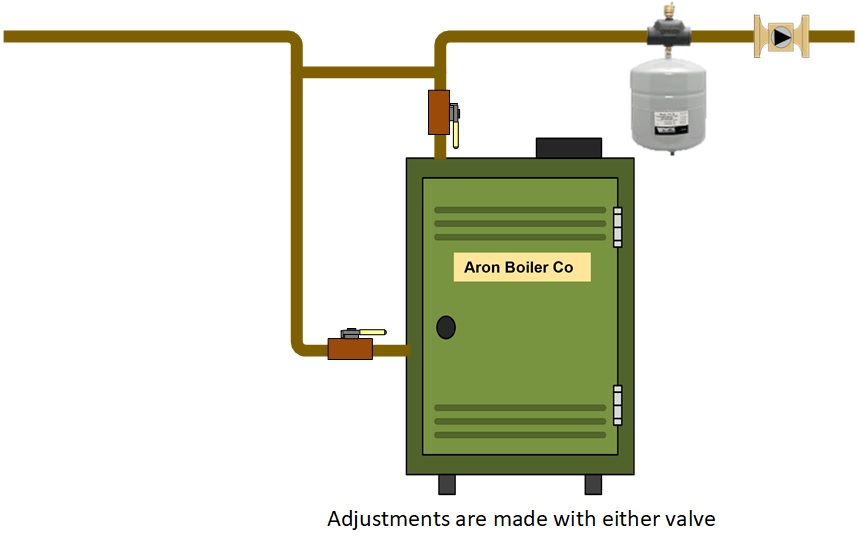
While the accompanying diagram shows the circulator on the return line, current best practices recommend mounting it on the supply side, directing flow away from the expansion tank connection. There is a prevailing belief in the industry that condensation in cast-iron boilers depends solely on the return water temperature. Although return temperature plays a significant role, factors such as the rate of temperature change and the boilerâs delta-T are also essential considerations. Industry professionals often cite recommended return temperaturesâsuch as 130F or 140F as thresholds for condensation risk; however, it is crucial to evaluate both temperature and flow velocity. Contemporary cast-iron boilers are engineered to operate effectively at lower return-water temperatures than their predecessors and to use less water. Manufacturer specifications should always dictate minimum allowable return temperatures, which, in the absence of explicit guidance, generally range between 20F and 40F.
A white paper by Gill Carlson of B&G, who developed the bypass piping concept, suggests that flue gas condensation and thermal stress arise primarily from the introduction of cold water into the boiler or from rapid movement of cool water through it. Consequently, addressing low return temperatures may require adjustments to the boiler's flow. A boiler bypass helps achieve a higher delta-T across the boiler, supporting optimal conditions for minimizing condensation. Ultimately, successful operation hinges on effective management of both water volume and flow rate.
System Bypass Piping
A system bypass is less effective for residential boilers, as it reduces temperature control and flow by recirculating water back into the boiler. In this setup, the circulator serves only the boiler, unlike a boiler bypass, where it serves the whole system. This approach is mainly used in commercial applications. Always check manufacturer specifications.
Circulator on Supply or Circulator on Return
Using a system bypass instead of a boiler bypass reduces system temperature control and overall flow, diverting some hot supply water back into the boiler, resulting in less heat output from the radiation due to reduced system water flow. When using a boiler bypass, the circulator supports the system; with a system bypass, the circulator supports the boiler. Refer to manufacturer specs for details.
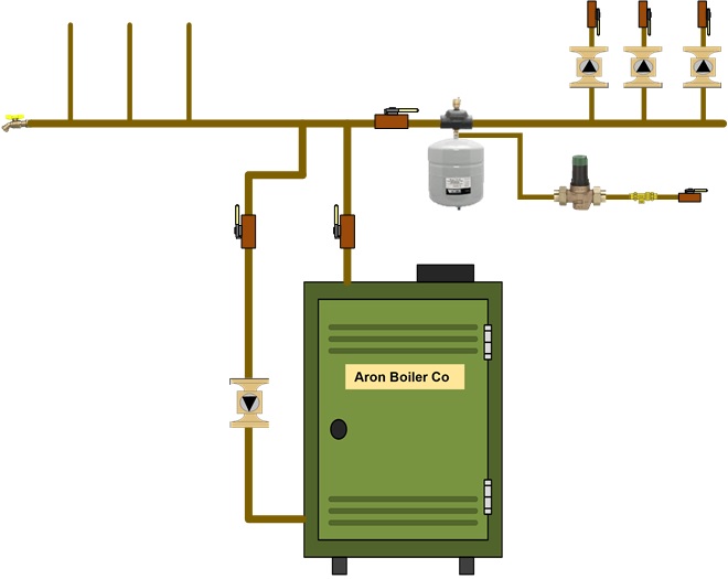
Primary/Secondary (P/S) piping
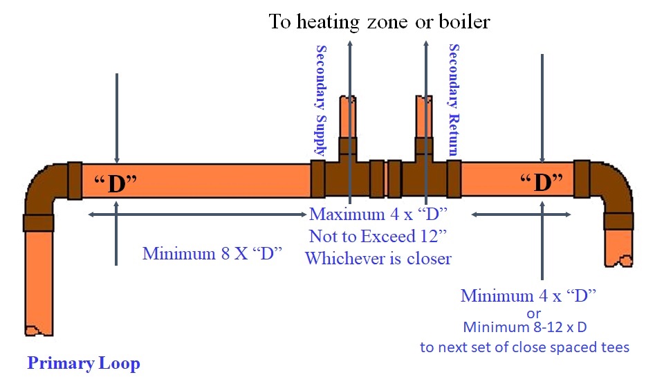
Primary/Secondary (p/s) Piping has become popular in residential systems over the past decade. It uses closely spaced tees for hydraulic separation, preventing interference between circulators. Boilers are usually placed in a primary loop or connected via secondary piping with tees. Cast-iron or steel boilers may require a bypass pipe, depending on the system design. Adjusting boiler flow helps control water temperature and reduce condensation; aim for a temperature rise of 25â40°F. Slightly opening the valve can help prevent short cycling. Follow these spacing guidelines: keep an 8x pipe diameter distance from a supply elbow, a maximum 4x diameter between tee centers, and a 4x diameter from a return elbow to a tee. Refer to diagrams for the two main p/s piping types.
Boiler Primary Loop. or Boiler as a Secondary Loop.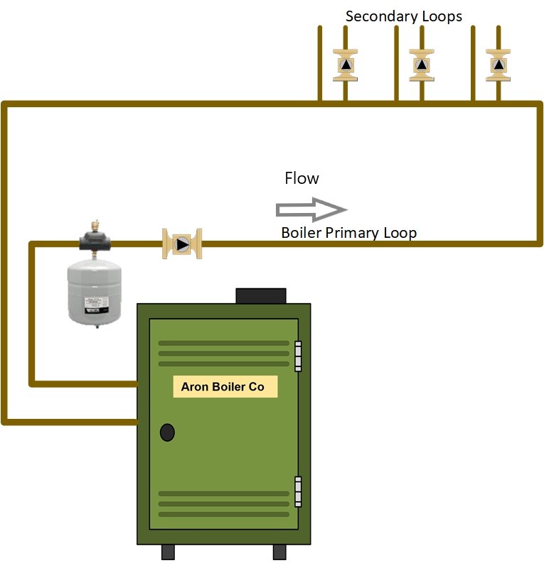
When installing cast-iron or steel residential boiler piping with primary/secondary (p/s) setups, a bypass pipe between supply and return may still be needed. If using a p/s loop with the boiler acting as the secondary, consider a system bypass or a partially closed valve on the supply to reduce flow and increase water temperature, preventing condensation. Adjust the flow for a 25F to 40F temperature rise; open the valve if short cycling occurs. Oversized boilers are less affected by bypass concerns. In a secondary loop, the boiler circulator remains unaffected by the primary loop.
For closely spaced tee applications in p/s systems, follow these spacing rules: keep elbows at least 8 times the diameter of the primary pipe from tees, space tee branches no more than 4 times the diameter (and not over 12"), and place return side elbows a minimum of 4 times the diameter from the tees. Generally, closer spacing is preferred.
The arrangement of the secondary zone piping on a boiler primary loop, which connects from the boiler and returns to it with all secondary zones branching off the loop using closely spaced tees. This is arranged from the shortest to the longest water-temperature loop. This configuration represents a multi-temperature water system. I typically recommend a boiler primary loop when multiple temperature zones are installed. In cases where most zones maintain the same water temperature, particularly when retrofitting from a cast-iron boiler, I prefer to use a single pipe with the boiler as a secondary. If all secondary zones share the same temperature but one zone has a different water temperature, manage the low-temperature zone using a mixing valve or another standard industry method.
Setpoint or Delta0T circulators
These can protect cast-iron boilers by adjusting water flow based on temperature changes. These devices monitor supply temperature or temperature differential and automatically change speed to optimize performance and prevent condensation or short cycling. By responding to sensor data and adapting to system demand, they improve boiler efficiency, extend equipment life, and maintain consistent heating.
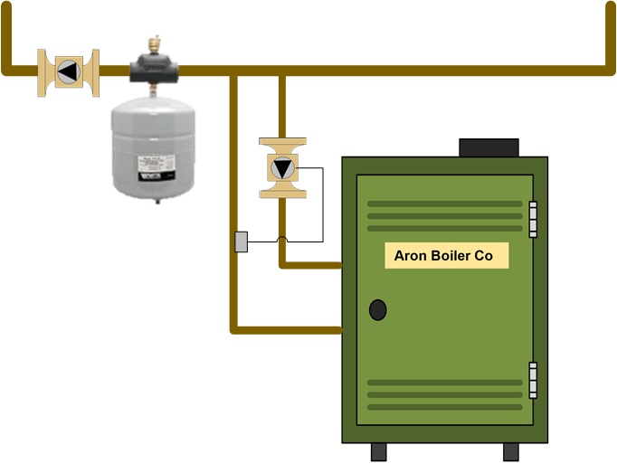
Setpoint Circulator
This device uses a sensor on the Boiler Supply pipe to regulate water flow based on the temperature of the Boiler Supply. If the supply falls below the set point, it slows down; as temperature rises, it speeds up, reaching maximum rpm if required. The circulator adjusts speed when other zones open and temperature changes. Recommended supply temperature is 130F to 140F.
Delta-T circulator
In primary/secondary systems, this device uses supply and return sensors to monitor temperature difference and adjusts its speed to maintain a set delta-T of 20F to 40F rise. It's suitable for manifold and primary/secondary setups; always confirm compatibility with high-efficiency boilers.
For manifold systems, the Delta-T circulator detects the boiler's temperature difference and changes flow as needed. As the delta-T nears the target, flow decreases to stabilize it.
Buffer Tanks
Buffer tanks are increasingly used because modern homes have more heating zones, reducing boiler short cycling, and the tank can be heated to higher temperatures to minimize flue gas condensation.
3 or 4 Way Valves
These valves protect cast iron and steel boilers by blending supply and return water. Mixing can be managed manually or automatically with a motor to adjust as the system cycles and zones change.
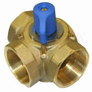
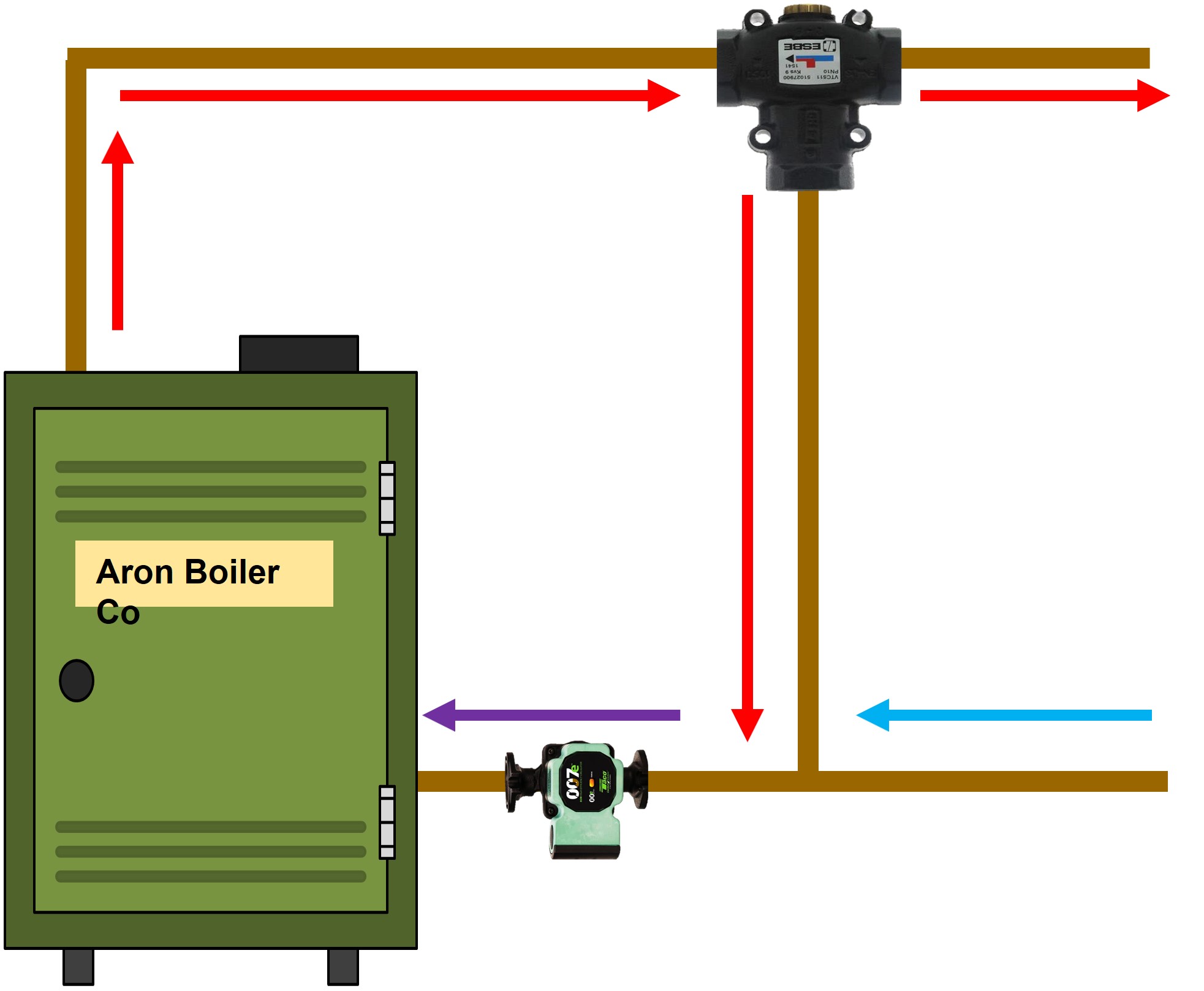
A 3-way valve has three ports: one connects to the boiler supply, one to the system supply, and one to the system return, integrated with tees. Using a 4-way valve without an actuator is not advised because system changes may occur; refer to the diagram for possible valve positions. While the 4-way valve can be manually adjusted for mixing, a motorized actuator ensures consistent boiler protection by responding automatically to temperature changes. This setup prevents flue gas condensation and thermal shock. See the position drawing for more details on valve operations under different conditions.
The 4-way valve has four ports: two connect to the system and two to the boiler. When motorized, an internal butterfly mechanism adjusts position to safeguard the boiler against flue gas condensation and thermal shock.
The 4-way valve has four ports: two connect to the system and two to the boiler. When motorized, an internal butterfly mechanism adjusts position to safeguard the boiler against flue gas condensation and thermal shock. This dynamic control enables the valve to precisely blend supply and return water as operating conditions change, providing a more reliable barrier against temperature extremes and ensuring the system responds efficiently to fluctuating heating demands without manual intervention.
See position drawing
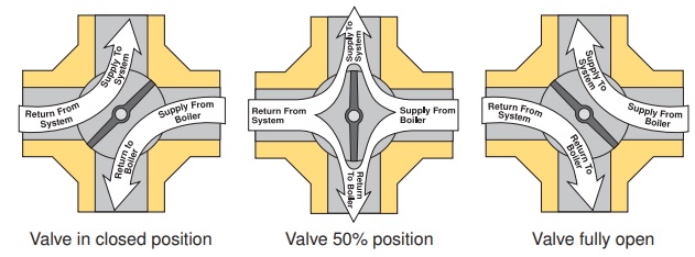
ESBE Thermic Valves
This 3-way valve operates by sensing water temperature, not electricity. Install it as a system bypass in boiler primary/secondary piping; hydraulic separation prevents flow issues. See the drawing for P/S and ESBE Thermic Valve with a cast-iron boiler. When the valve is closed, it blocks the flow of cool boiler water. As the water heats, the valve mixes return and boiler water. Once the temperature is sufficient, the valve opens, stopping flow through the bypass pipe.
Thermic valve open to the system when the boiler water gets hot enough Thermic valve in mix position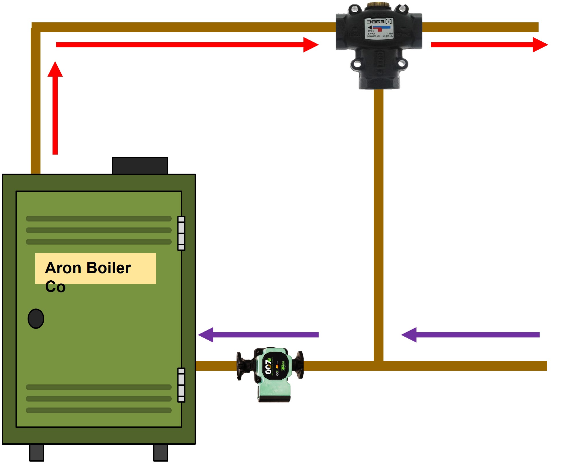
Thermic valve open position Disclaimer: The information found on this website is for informational purposes only. All preventive maintenance, service, and installation should be reviewed on a per-job basis. Any work on your heating system should be performed only by qualified, experienced personnel. Comfort-Calc and its personnel accept no responsibility for improper information, application, damage to property, or bodily injury from applied information found on this website.