Sizing Gas Piping Layout
- When replacing the heating appliance
- Replacing a gas boiler and gas tank-type water heater with a combi boiler (heat and domestic Hot water)
- New construction with natural and LP gas
- When the existing system cannot maintain proper incoming gas pressure
- Converting oil to gas
- To determine if the current gas piping can adequately handle the addition of another gas appliance.
There are three basic types of calculations for residential gas lines.
There are four types of pipes used for residential gas.
Sizing Residential Iron Pipe Gas Lines
We must first do a fact-finding mission. We need to understand the layout, the existing appliance sizing, and how many Btu/h we will be adding in Btus or CPH.
Here is a list of what is needed.
- Total Load -Connected load by appliance and Btu/h
- Btu's or CFH chart-We will supply this for this exercise. It is best to get a chart from the code books.
- Drawing -Proposed piping layout, make the measurement as accurate as possible
- Fuel Type -Choose Natural or LP gas
- Heating Value -Get this from the fuel supplier
- Longest Pipe - Dertemine the longest pipe from the meter to furthest appliance
- Pressure Drop -Your choice. We suggest 0.5" w.c. or 0.3" w.c.
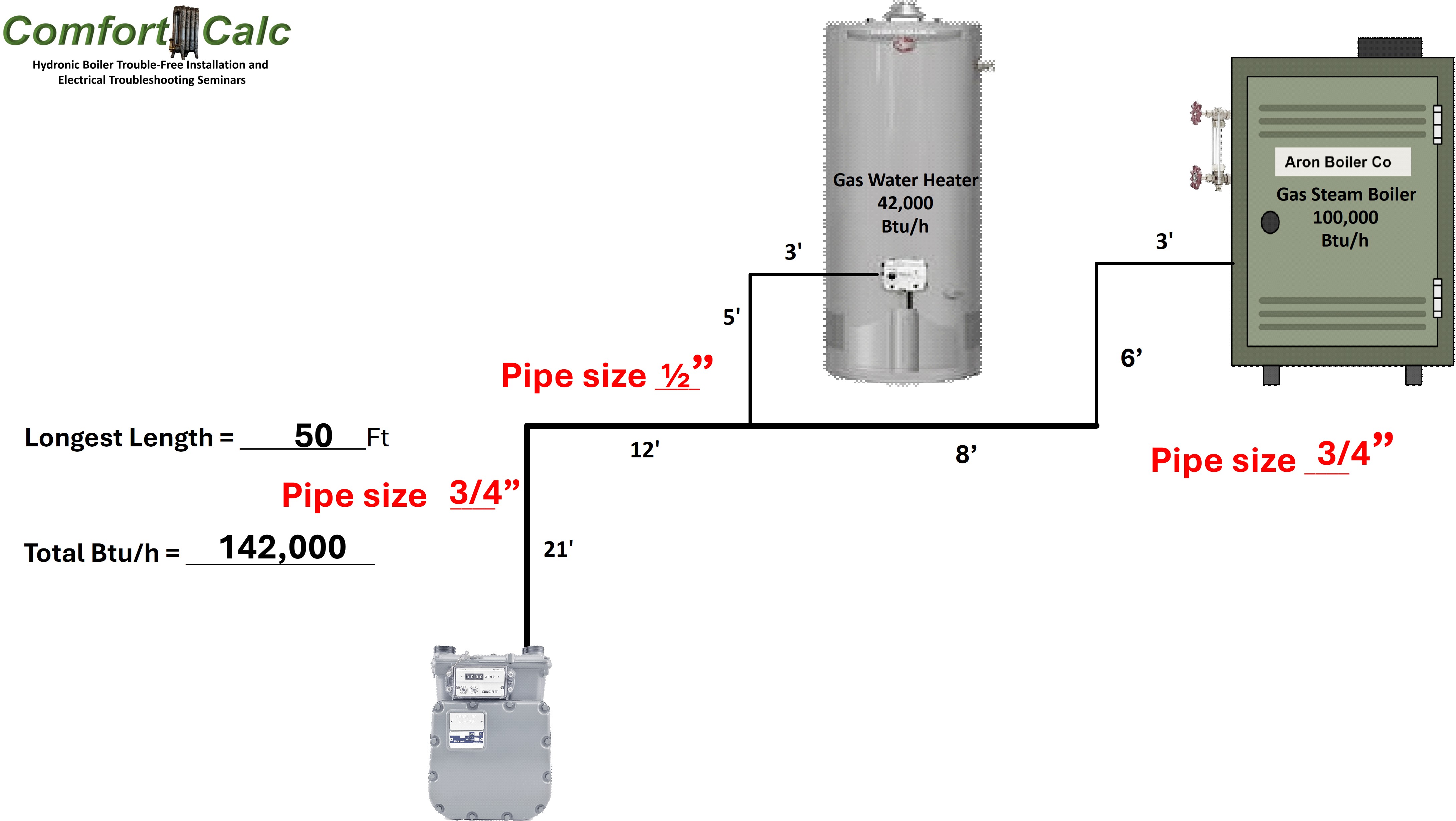
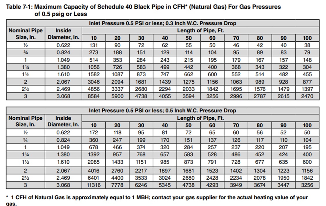
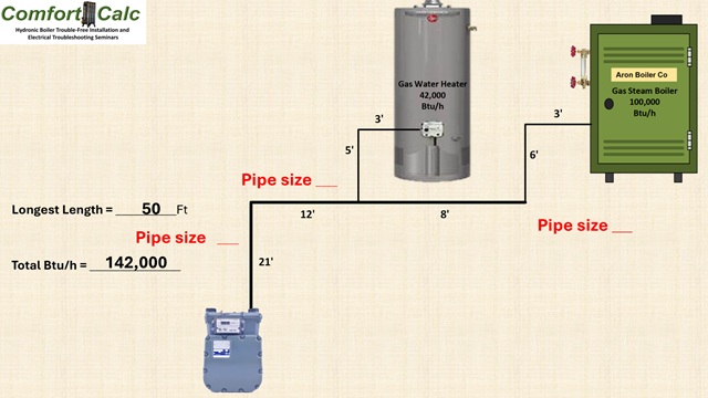
Calculations for the longest-length method determine the longest pipe from the meter or pressure regulator to the furthest appliance. In the above example, the longest pipe is 50 ft. This means that for each application, you must always use the 50-foot line or column on the chart. Here is the chart for Natural Gas. I have highlighted the 50-foot line. When calculating the longest pipe, if the pipe is 1 foot over the chart length, go to the next line. For instance, if the pipe is 41 ft, use the 50 ft row or column. At 51 ft, go to the 60-foot line. If a chart you are using for natural gas is using Cubic feet, divide the Btus by 1000, and if it is LP, divide btu's by 2616.
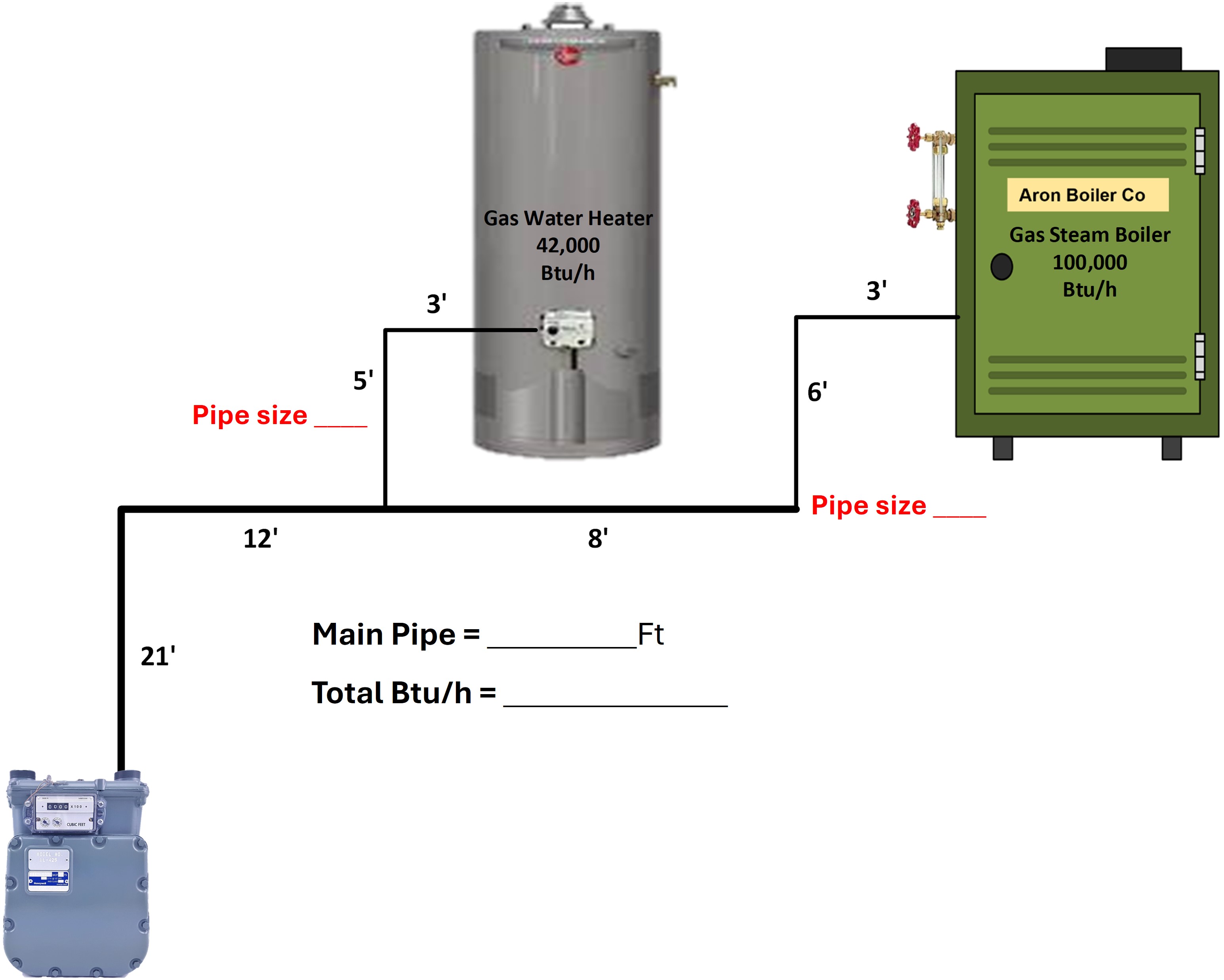
Here is the information we gathered
- Natural or LP gas - We'll choose Natural gas
- Water Heater - 42,000
- Boiler - 100,000
- Btu/h or Cubic CFH - Let's CFH/h
- Total Load - (42,000 + 100,000) 142,000 Btu/h (below)
- Longest Pipe - 50 ft. (21'+ 12'+ 8'+ 6'+ 3')
- Pressure Drop -Let's choose 0.3" w.c. PD
The overall length of the pipe to the most distant appliance measures 50 feet. Select that column and identify the value that is at least 142,000 Btus divided by 1000, which equals 142 CPH, corresponding to a 1" pipe. Checking the 50' column for a 3/4" pipe, the value is just 114 CPH or 114,000 Btus, and would not be enough gas volume.
Referring to this chart, we will select the 50-foot pipe length and keep in mind that we are using the top chart heading for the 0.3" PD chart.
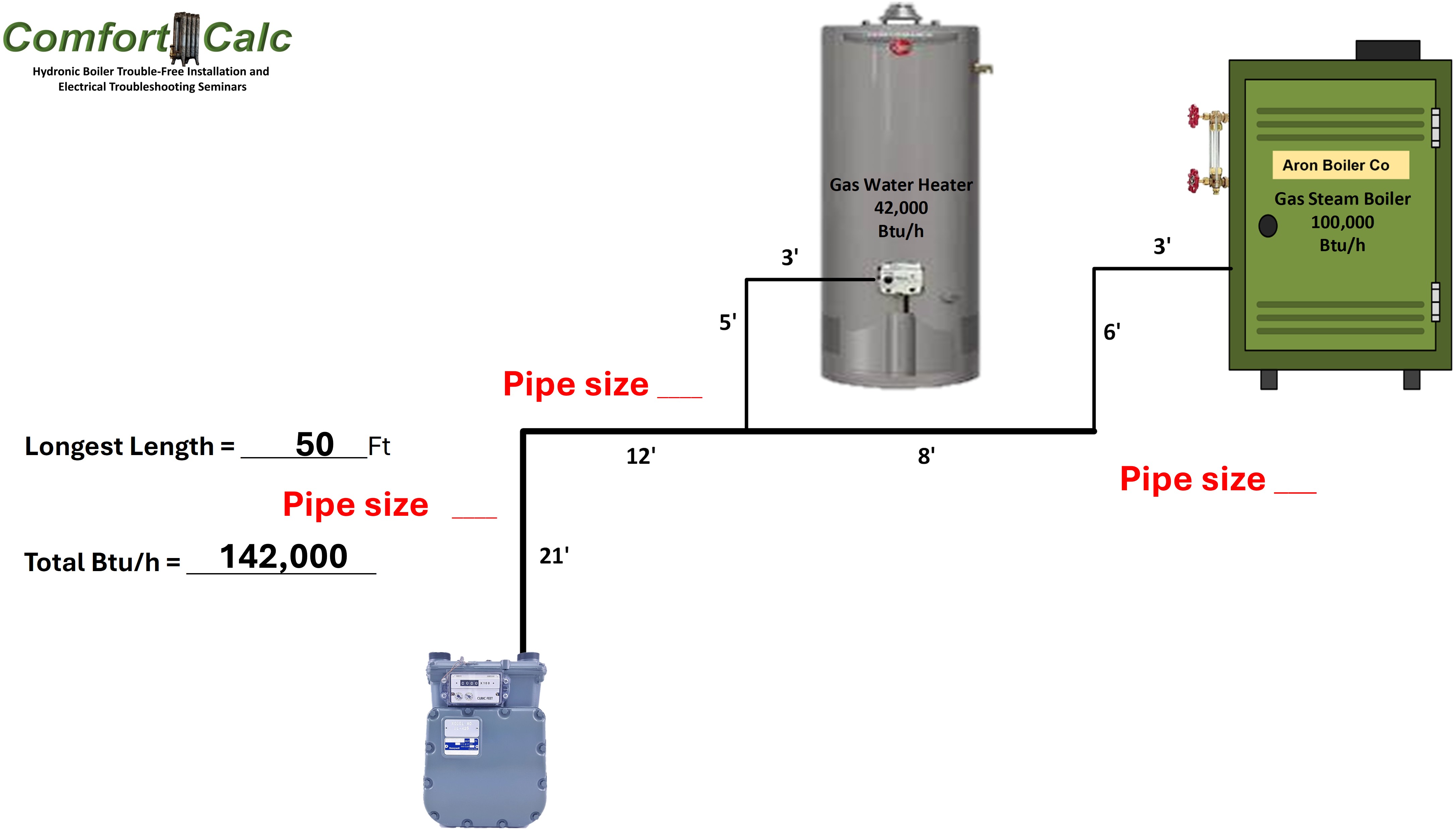 Let's finish this calculation for both the boiler and the water heater, starting from the main line to the appliances. Since we chose the longest-loop method, we will stay within the 50 Ft column. Next, we will figure out the pipe sizes from the main pipe as it extends over and down to the appliances.
We will use the CFH only for the boiler. Remember to convert to natural gas CPH: 100,000/1000 = 100. Look down the column until we reach a number equal to or greater than 100. Go left and see 3/4" pipe.
Apply the same calculation for the water heater: 42,000 divided by 1,000 equals 42. Then, you would stop at 55 and go left to check the 1/2" size.
 Compare using the 0.3 and 0.5" w.c. Pressure drop, look at the same drawing, and use the 0.5" w.c. pressure drop chart. It should look like this.