
Ask Your Boiler and System Questions or Leave Your Comments Here
Caution:All drawings are conceptual drawings for illustration purposes only and may be incomplete. More specific drawings may be needed for your application.
Common Mistakes made with Primary/Secondary (P/S) Piping
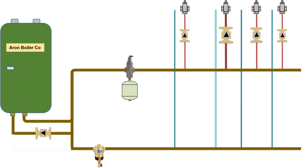
The problem I'll be discussing is using a boiler primary loop and not installing close-spaced tees for each zone. Instead, the installation has all zone supply pipes and all the zone return pipes somewhere after the supply pipes. This is a poor attempt at integrating primary, secondary, and manifold piping. The only thing accomplished is eliminating hydraulic separation. This, in many cases, causes ghost flows. Unfortunately, when pointing this out on a jobsite, the response one normally hears is, I do this all the time and never had a problem before. Well, Bucco, you have the problem now. You had it before, but not bad enough to show up. When the conditions are right, it becomes noticeable to the point of being a problem. Since you never received the complaint, it doesn't mean it wasn't happening. However, in this application, the resistance or flow in one loop differs significantly from that in another loop. Not only is the consumer overheating a given zone, but his attitude is also being heated; fortunately, he doesn't realize he has a higher fuel bill. The main reason this does not work is that there is no hydraulic separation between the boiler primary loop circulator and the zone circulators. If you're unsure what I mean, refer to the 'Primary Secondary Basics' page in the menu on the left, or consider purchasing the 'Primary Secondary' seminar for a more detailed explanation. Here are four reasons for the ghost flows in the system.Problem #1
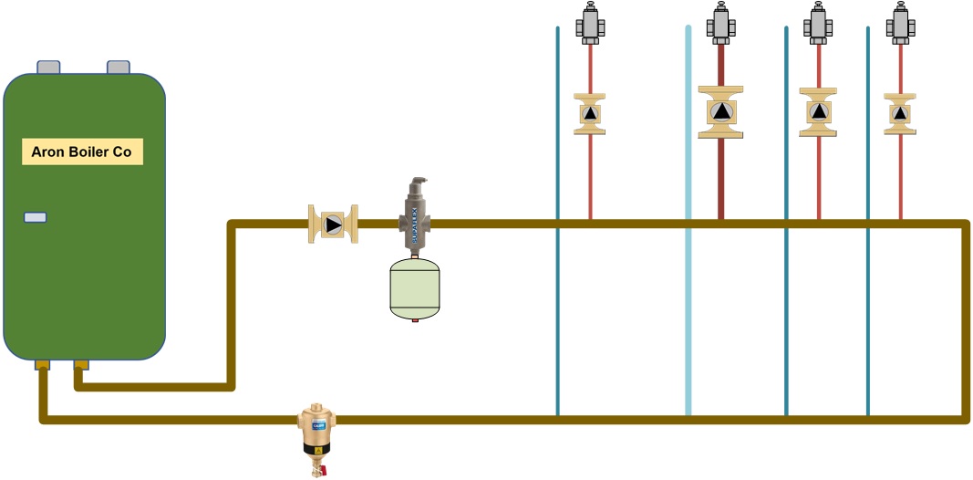
The given here is that there are working flow checks or check valves on the zones.
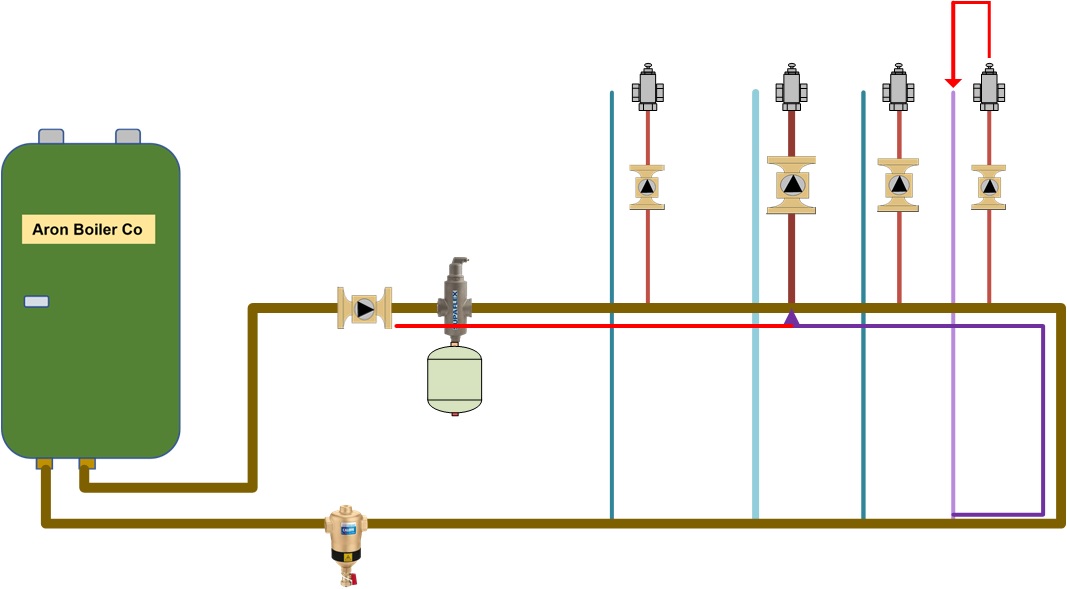
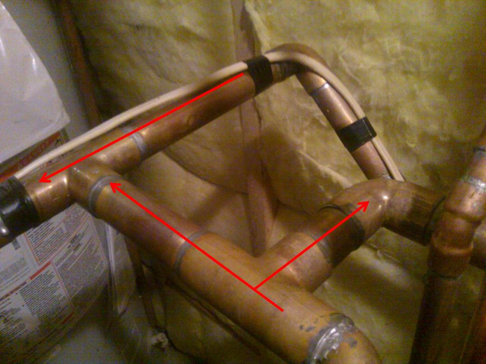
The zone with the ghost flow is moving water up through its flow check valve, through the zone, down the return, and back to the zone that is needing the extra flow.
Below the arrows is the ghost flow that is being created by the larger zone.
How do we fix this? Here are two solutions.
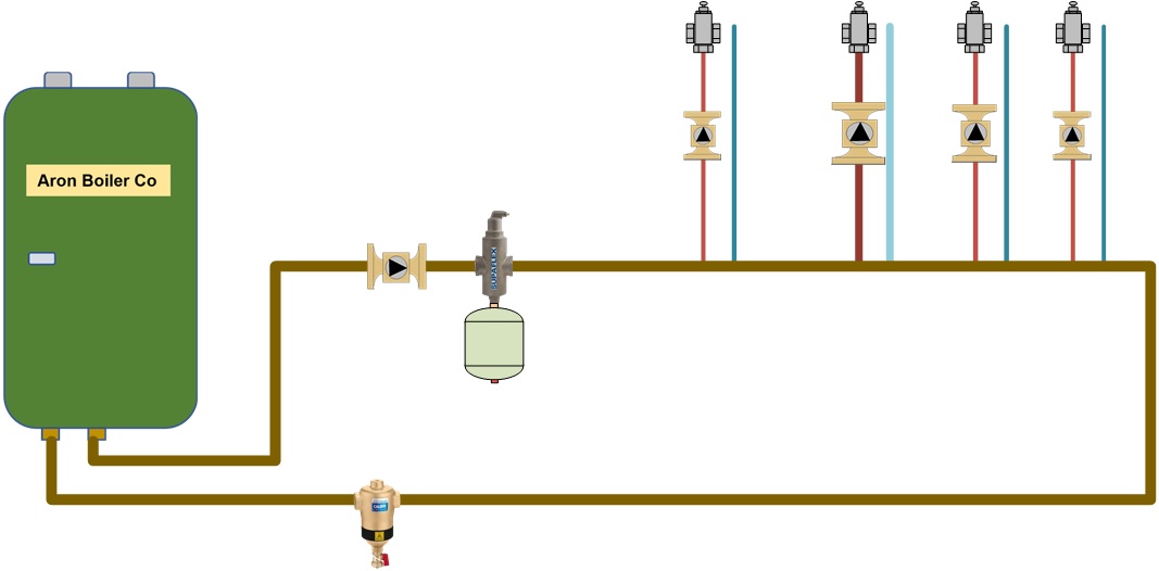
- Remove all the returns from the bottom of this loop and put a return tee after each zone supply tee. Note, the flow from the boiler primary loop must enter the zone supply tee first and return as close as possible after the zone supply tee. The orientation of the zone return tee can be fed from the bottom. The idea that the supply tee points up and the return tee points down is not an issue. Be aware that piping this way could create a new problem. As the number of zones increases, the supply water temperature to the latter zones will be tempered down due to blending return in the boiler primary loop from prior zones that have run.
- Cut the boiler primary loop on the right side of this drawing and cap the two pipes to create a supply manifold and a return manifold. However, we are not done yet. Now, on the left side of the drawing, cut the pipes and tie the two pipes together so that the supply and return manifolds are combined into one pipe. Insert two closely spaced tees and pipe the boiler into them, creating hydraulic separation between the boiler loop and the system loop. Ensure that you move the circulator to the boiler loop. There is no need to have a circulator added to the system side of the piping, as each zone has its own circulator. Problem solved and lesson learned.
Problem #2

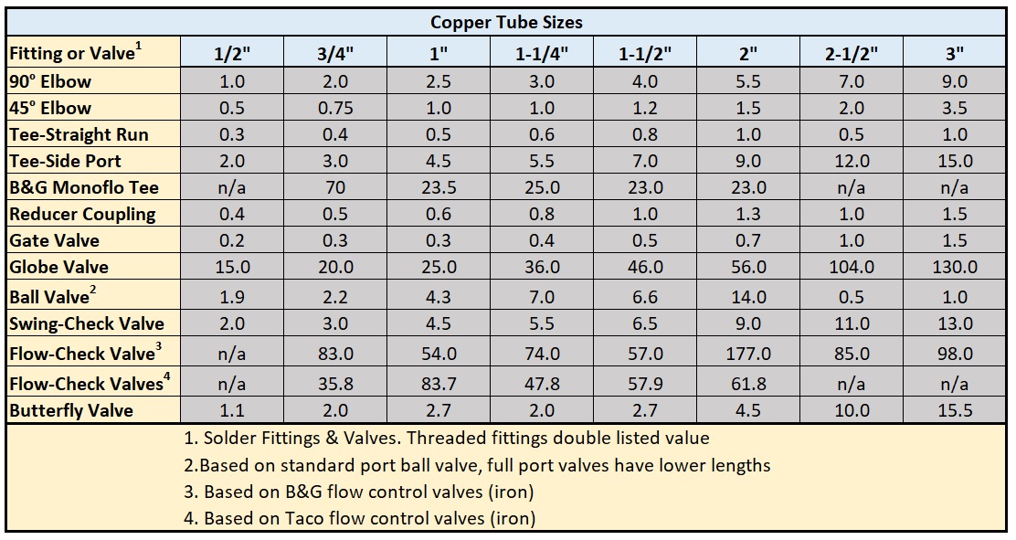
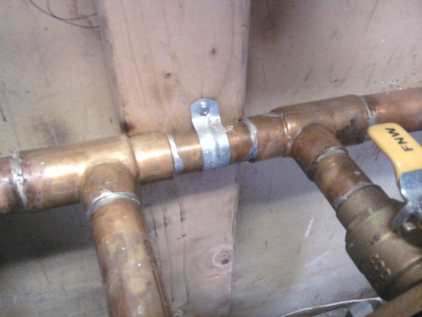
Putting a 1-1/4” elbow between the tees will add about 3 EFP. A valve could add up to 10+ EFP.
Problem #3
We decided to shorten the highest horizontal runs, and the problem went away.
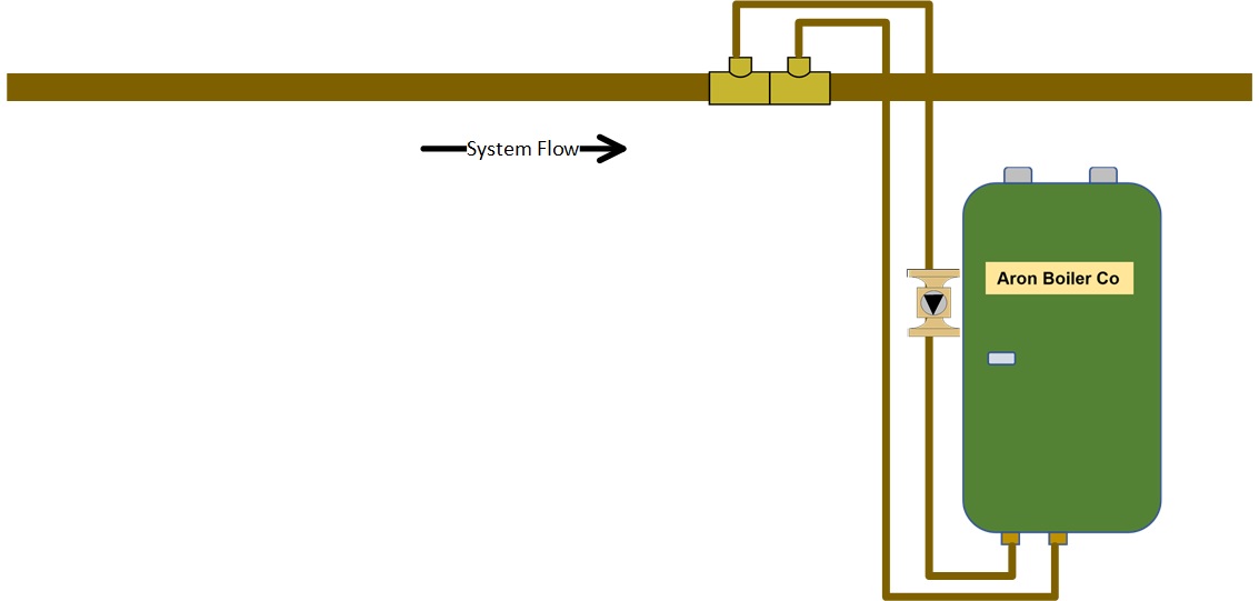
Bring the secondary boiler piping into the side or the bottom of the primary pipe. Do not chance having these problems.
Problem #4
Problem #5
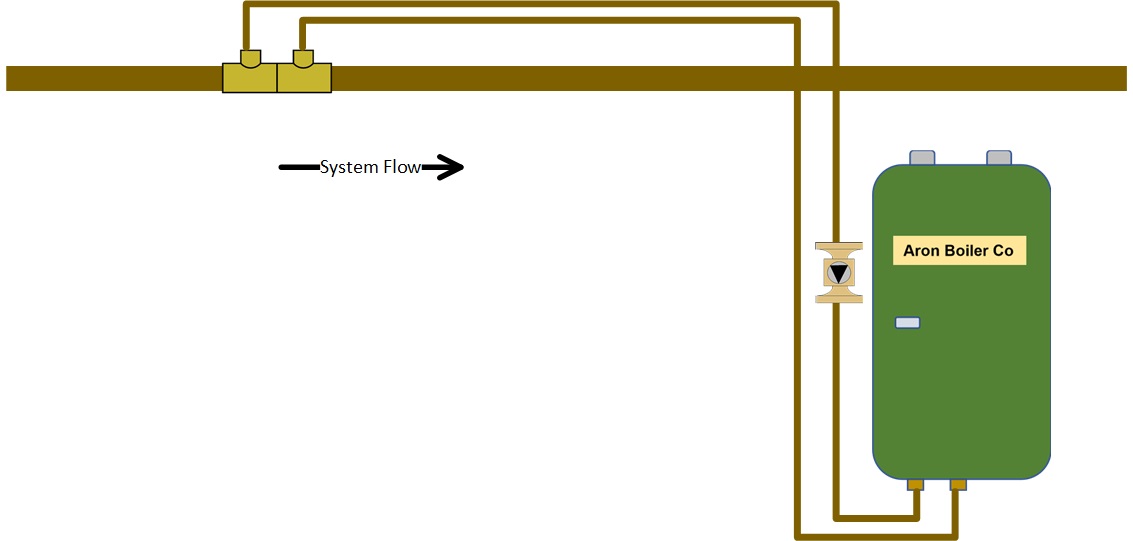
One of the more common problems I experience is that one of the tees is rotated 90 degrees. This changes the flow in and out of the secondary zone, be it the boiler or a heating zone. As stated above, we are seeking a minimal pressure drop between the tees. We need the same resistance in the secondary zone as we have out of the secondary zone. If you read the P/S tutorial, you know the maximum distance between the tee branches, also called the bull of the tees, is not to exceed 4 times the diameter of the primary pipe, not to exceed 12” whichever is closer. What is the problem with this first drawing?
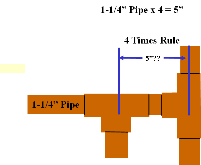
Since every fitting has an equivalent feet of pipe (EFP) plus all the piping the water passes through, which is a resistance to flow, this can create a problem. Since the secondary loop is always piped away and returned to the branch of the tees, we need to examine the EFP of the tee. See the EFP chart link on this page, but if we look at 1-1/4" tees, we can see the flow into the tee and out of the branch is equal to 5.5 EFP. Remember, we need the same resistance into the secondary zone as we have out of the secondary zone to maintain the correct flow. The flow into and through the tee is 0.6 ft. of pipe. This means that one tee route has a 5.5 EFP, and the other tee route has a 0.6 EFP. The result is an unbalanced flow. In the above example, we can measure the distance and if it measures with a rule to 5", we might think we are OK. But looking at the EFP, we are about 6 feet of pipe.
Disclaimer: The information found on this website is for informational purposes only. Any preventive maintenance, service, or installation should be reviewed on a per-job basis. Any work performed on your heating system should be performed by qualified and experienced personnel only. Comfort-Calc or its personnel accepts no responsibility for improper information, application, damage to property or bodily injury from applied information found on this website as it should be reviewed by a professional.