
Circulator Sizing
To properly size your circulator will need to know the load and pipe size to continue.
There are three ways to size a circulator, good, better, and best. I personally use the better or middle one most of the time. The major differences between the three is more accurate circulator sizing as we proceed from good to best. I will cover all three.
Before we start to size a circulator, we must know what the load is, how many btu’s we need to carry through the zone and what size pipe we need to carry that load. We have shown you how to determine that on the pipe sizing page.
B&G Rule of thumb (good)
This one is simple but is the sloppiest calculation and will usually cause you to be one circulator size larger than needed.
- Measure the length of the heat zone pipe from the boiler, all the way around the loop and back to the boiler.
- Multiply the total length of the zone by 1.5 to account for the fittings
- Multiply times .04 for pipe friction.
The formula is;
FH =( EFP x 1.5*).04
FH = Feet of head
EFP = Equivalent feet of pipe
1.5 = assumption for fittings
.04 = friction loss for 100’ of pipe
Measure 130 ft of pipe in a given zone
FH=(130 x 1.5)*.04
FH=195*.04
FH=7.8
Copper Tube Handbook (better)
We will use the same zone as above of 130 ft.
PSI =( EFP x 1.5*)*PL
PL = Pressure Loss
EFP = Equivalent feet of pipe
1.5 = assumption for fittings
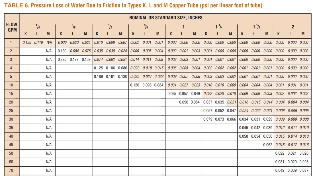
Measure 130 ft of pipe in a given zone of type M copper
PSI=(130 x 1.5)*.015 (4 gpm flow)
PSI=195*.015
PSI=2.9 PSI
Since Chart 6 is calculated in PSI loss per lineal foot of pipe we must convert it to Feet of Head. One pound of pressure = 2.31 ft. Yep another calculation.
Convert PSI to Ft. Hd.
Ft. Hd. = PSI*2.31
2.9 * 2.31 = 6.7 Ft. Hd.
Now run the same formula at a 3 gpm (30,000 loop) flow rate using M tubing and the flow is now 4 Ft. Hd. instead of 6.7 FT. Hd.
If I am choosing a flow rate of 2.5 gpm (25,000 loop) I would split the difference of 0.007 which is halfway between 0.004 and 0.009 pressure drop. The Ft. Hd. now would be 3.13 which is quite different from the B&G rule of thumb of 8 Ft. Hd.
Could this slightly undersize the circulator? Yep, but since the circulator will run on the curve it will pump more than your calculation unless it falls right on the line so circulator will not be undersized.
Oversizing the circulator will not only cost more to buy and run but move too much water which can affect the boiler dependent on type of installation and boiler type. As we increase the velocity of the water we increase the resistance to flow. Therefore, I usually use this calculation.
If you choose any of these options including the option below, you will need to choose the proper circulator
Circulator Sizing Formula (best)
Feed this into the formula and have the most exact circulator sizing information. Personally, I feel for residential applications the calculation using the Copper Tube Handbook number is best.
HL=k x c x L x (f1.75)
HL is head loss
k = Tubing size - the size tubing being used
c = Correction factor for fluid type - what type of fluid you are using
I = Equivalent length of piping including all the valves, fittings, air separator, zone valves, etc. converted to equivalent length of pipe.
f(1.75) = Flow rate through pipe raised to the power of 1.75
Flow Rate Factor (f)
|
Flow Rate |
Raised to 1.75 |
| 0.5 | 0.297 |
| 1 | 1.000 |
| 1.5 | 2.033 |
| 2 | 3.364 |
| 2.5 | 4.970 |
| 3 | 6.839 |
| 3.5 | 8.956 |
| 4 | 11.314 |
| 4.5 | 13.903 |
| 5 | 16.719 |
| 6 | 23.002 |
| 7 | 30.125 |
| 8 | 38.055 |
| 9 | 46.765 |
| 10 | 56.234 |
| 12 | 77.369 |
| 14 | 101.327 |
| 16 | 128.000 |
| 18 | 157.229 |
| 20 | 189.148 |
| 25 | 279.508 |
| 30 | 384.558 |
| 31 | Exceeds Limits |
| Flow | Pipe Size | Value of k | |
| 1.0 | 2.0 | 3/8" Copper | 0.0484 |
| 1.6 | 3.2 | 1/2" Copper | 0.0159 |
| 3.2 | 6.5 | 3/4" Copper | 0.00295 |
| 5.5 | 10.9 | 1" Copper | 0.000845 |
| 8.2 | 16.3 | 1-1/4" Copper | 0.000324 |
| 11.4 | 22.9 | 1-1/2" Copper | 0.000146 |
| 19.8 | 39.6 | 2" Copper | 0.0000397 |
| 30.5 | 61.1 | 2-1/2" Copper | 0.0000142 |
| 43.6 | 87.1 | 2" Copper | 0.0000061 |
| "c" Correction Factor for Fluid Temperature | ||||
| Average Fluid Temp | 100º f | 140ºf | 180ºf | |
| Water | 1.095 | 1.000 | 0.933 | |
| 30% Propylene Glycol | 1.353 | 1.187 | 1.088 | |
| 50% Propylene Glycol | 1.582 | 1.349 | 1.225 | |
Disclaimer: The information found on this website is for informational purposes only. All preventive maintenance, service, installations should be reviewed on a per-job situation. Any work performed on your heating system should be performed by qualified and experienced personnel only. Comfort-Calc or its personnel accepts no responsibility for improper information, application, damage to property or bodily injury from applied information found on this website.